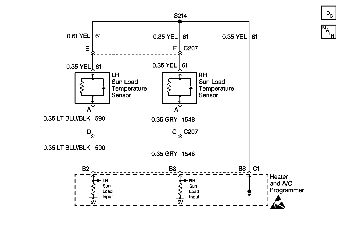
Circuit Description
The right sun load temperature sensor is a light sensitive photodiode that controls signal voltage to the heater and A/C programmer. This photodiode is different from standard thermistor sensors and resistance measurements will not produce accurate results. The heater and A/C programmer monitors voltage on CKT 1548 to the sensor. When the sensor is in direct sun light, the heater and A/C programmer reads a low signal voltage at terminal B3, connector C2. When the sensor is shaded, the signal voltage increases. Signal voltage varies from 5 V (open circuit) to 0 V (short circuit).
Conditions for Setting the DTC
| • | The ignition is on. |
| • | The circuit is open or shorted. |
Action Taken When the DTC Sets
| • | A default value of dark or no sun load will be used by the heater and A/C programmer. |
| • | The default value will allow the system to operate. |
Conditions for Clearing the DTC
| • | Use a Scan Tool . |
| • | A history DTC will clear after 50 consecutive ignition cycles have occurred without a malfunction. |
| • | Battery voltage to the body control module is interrupted. |
Test Description
The numbers below refer to the step numbers on the diagnostic table.
-
Perform the Body Control Module (BCM) Diagnostic System Check before continuing with the diagnosis of this DTC.
-
This step determines whether the sensor is operational.
-
This step determines if the DTC was set in error.
-
This step determines if the malfunction is the sensor, or an open or a short, in a circuit.
-
This step determines if the heater and A/C programmer, or an open or short, is causing the malfunction.
-
The Scan Tool tests for proper sensor operation. Clear all of the DTC's after the repair procedures are complete.
Step | Action | Value(s) | Yes | No |
|---|---|---|---|---|
Did you perform the BCM Diagnostic System Check? | -- | Go to Step 2 | Go to Diagnostic System Check - Body Control System in Body Control System | |
Did the sensor counts increase from the noted value? | -- | Go to Step 3 | Go to Step 4 | |
Did the DTC reset? | -- | Go to Step 4 | ||
Does the voltage equal the specified value? | 4.5-5.5 V | Go to Step 8 | Go to Step 5 | |
5 | Measure the voltage between the sun load sensor harness connector terminal A and ground. Refer to Measuring Voltage in Wiring Systems. Does the voltage equal the specified value? | 4.5-5.5 V | Go to Step 9 | Go to Step 6 |
6 | Measure the voltage between the heater and A/C programmer terminal B3 and ground. Refer to Measuring Voltage in Wiring Systems. Does the voltage equal the specified value? | 4.5-5.5 V | Go to Step 7 | Go to Step 10 |
7 | Repair an open or a short in CKT 1548 (GRY). Refer to Wiring Repairs in Wiring Systems. Is the repair complete? | -- | Go to Step 12 | -- |
8 | Replace the right sun load temperature sensor. Refer to Sun Load Sensor Replacement . Is the repair complete? | -- | Go to Step 12 | -- |
Are all of the HVAC sensor DTCs present? | -- | Go to Step 10 | Go to Step 11 | |
10 |
Is the repair complete? | -- | Go to Step 12 | -- |
11 | Repair an open or short in CKT 61 (YEL). Refer to Wiring Repairs in Wiring Systems. Is the repair complete? | -- | Go to Step 12 | -- |
Is the system operating properly? | -- | Go to Diagnostic System Check - Body Control System in Body Control System | -- |
