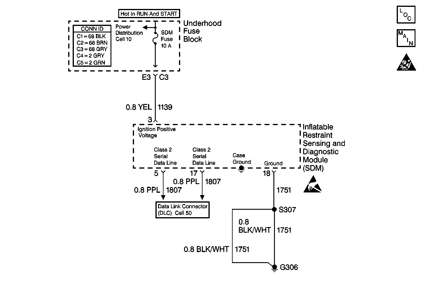
Circuit Description
Battery positive voltage (B+) is supplied to the SDM when the ignition switch is in the RUN position via CKT 1139. The sensing and diagnostic module (SDM) learns the source ID of the battery voltage report message. The SDM monitors this message every 300 milliseconds.
Conditions for Setting the DTC
The ignition positive voltage level falls below 9 volts for approximately 1 second or more and the ignition switch is not in START.
Action Taken When the DTC Sets
| • | Stores a DTC B1327 in the SDM memory. |
| • | The SDM will not set any communication DTCs. |
| • | No driver warning message will be displayed for this DTC. |
Conditions for Clearing the DTC
The ignition positive voltage level rises above 9.5 volts for approximately 1 second.
Diagnostic Aids
The SDM will not check for low ignition positive voltage during and for 2 seconds following the engine START mode. This ensures that DTC B1327 will not erroneously set.
Test Description
The numbers below refer to the step numbers on the diagnostic table:
-
Perform the entire SIR Diagnostic System Check before continuing with the diagnosis of this DTC.
-
Checks that DTC was not set erroneously.
-
Determines whether the malfunction is in the charging system or the SDM.
Step | Action | Value(s) | Yes | No |
|---|---|---|---|---|
Was the SIR Diagnostic System Check performed? | -- | Go to Step 2 | ||
Is Ignition 1 greater than the specified value? | 9 V | Go to Step 3 | ||
Is the voltage less than the specified value? | 9 V | Go to Charging System Check in Engine Electrical |
