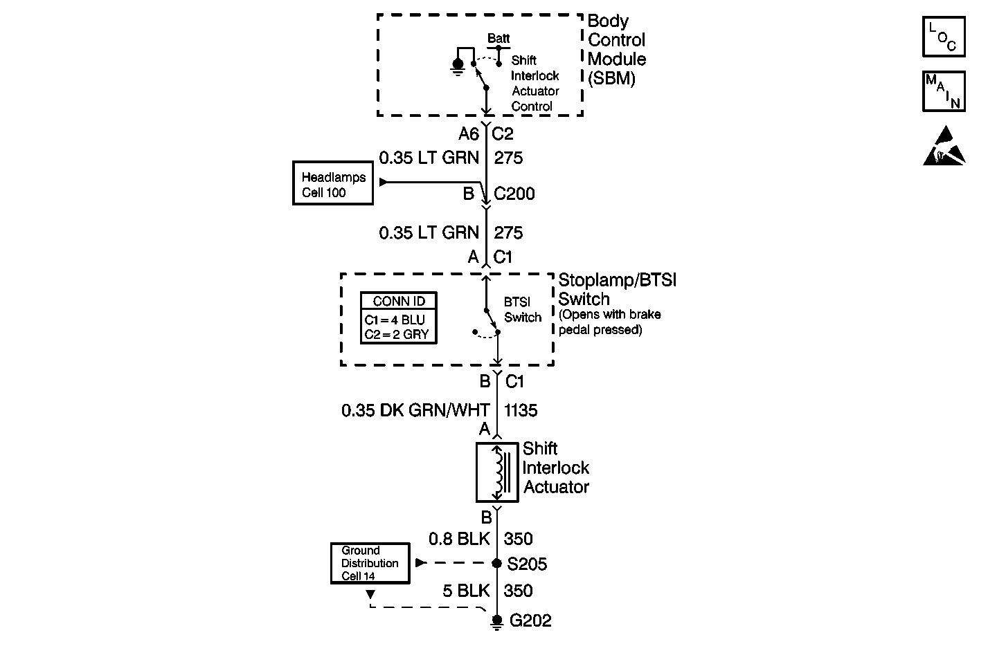
Circuit Description
The body control module (SBM) supplies voltage to CKT 275 while the following conditions occur:
| • | The ignition switch is in RUN. |
| • | The transaxle is in the PARK position. |
When you press the brake pedal, the following functions occur:
| • | The stoplamp/BTSI switch opens the BTSI circuit. |
| • | The shift interlock actuator disables. |
The SBM monitors the output. The SBM determines the actual voltage at terminal A6 every 0.3 seconds.
Conditions for Setting the DTC
The SBM detects the voltage on terminal A6 for more than 0.1 seconds.
Action Taken When the DTC Sets
| • | DTC B0803 store in the SBM memory. |
| • | No driver warning message displays for this DTC. |
Conditions for Clearing the DTC
| • | The battery voltage is no longer detected by the SBM on terminal A6. |
| • | The history DTC clears after 50 consecutive ignition cycles if the condition for the malfunction is no longer present. |
| • | Use the on-board diagnostic (clearing DTC) feature. |
| • | Use a scan tool. |
Diagnostic Aids
An intermittent short to battery positive voltage (B+) in CKT 275 or CKT 1135 may cause an intermittent malfunction to occur.
If the DTC is a history DTC, the condition may be intermittent. Try performing the tests while moving the following components:
| • | The wiring |
| • | The connectors |
Moving the wires may often cause the malfunction to appear.
Test Description
The numbers below refer to the step numbers on the diagnostic table.
-
Always perform the SBM Diagnostic System Check before attempting to diagnose a DTC B0803.
-
This step determines if a short to battery positive voltage (B+) exists on CKT 275 or CKT 1135.
-
This step determines if the short to voltage is located in CKT 275 or CKT 1135.
Step | Action | Value(s) | Yes | No |
|---|---|---|---|---|
Did you perform the Diagnostic System Check - Body Control System ? | -- | Go to Step 2 | ||
Is the measured voltage in the specified range? | 10-15V | Go to Step 3 | Go to Step 6 | |
Press the brake pedal. Is the measured voltage in the specified range? | 10-15V | Go to Step 5 | Go to Step 4 | |
4 | Repair the short to battery positive voltage (B+) in CKT 1135. Is the repair complete? | -- | Go to Step 7 | -- |
5 | Repair the short to battery positive voltage (B+) in CKT 275. Is the repair complete? | -- | Go to Step 7 | -- |
6 |
Is the repair complete? | -- | Go to Step 7 | -- |
7 |
Are all of the DTCs cleared? | -- | System OK |
