Removal Procedure
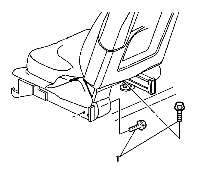
- Remove the seat assembly. Refer to Seat Replacement . Before removing seat from the vehicle position the inner seat adjuster rail even with the outer seat adjuster rail.
- Place the seat upside down on a clean protected surface.
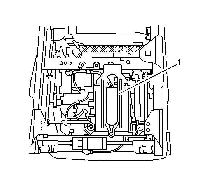
- Remove the front fasteners from the memory seat module bracket (if equipped).
- Remove the horizontal nut cage bolts (4).
- Remove the outer rails (3, 6).
- Remove the wiring harness to the motor.
- Remove the wiring harness to the position sensors (if equipped with memory seats).
- Remove the horizontal gear box fasteners (2, 5).
- Spread the rails apart to disengage the horizontal motor assembly.
- Remove the drive assembly (7) by pulling upward.


Installation Procedure
Tools Required
J 36169-A Fused Jumper Wires
- Lubricate the nylon bushings on the "L" bracket with grease.
- Ensure the nut cages are both bottomed out on the horizontal drive housing and insert the drive.
- Insert the lead screw end into the nylon bushing.
- Install the fasteners (2, 5) securing the horizontal drive housing to the inner rail.
- Slide the outer rails (3 & 6) over the inner rails (1). Line up the horizontal nut cages with the nut brackets on the outer rails.
- Install the nut cage fasteners (4).
- If the vehicle is equipped with memory seats, install the memory seat module (1) bracket fasteners.
- Lubricate the lead fastener with grease.
- Power the adjuster fully forward by using the J 36169-A to apply battery positive voltage at the beige wire pin of the horizontal drive motor connector body and battery ground to the green wire pin. Make sure the adjuster bottoms on the housing.
- Loosen the nut cage bolts (4) and retorque.
- Power the adjuster back to full rearward position by reversing the J 36169-A connections used in the previous step. Ensure the front end of the inner rail is even with the front end of the outer rail.
- Connect the electrical connectors.
- With the aid of an assistant, install the seat to the vehicle. Refer to Seat Replacement .
- Ensure the inboard rail bolt has a washer present.
- Test the seat operation.

If the vehicle is equipped with memory seats, slide the memory seat module bracket ears into the horizontal motor bracket.
Notice: Use the correct fastener in the correct location. Replacement fasteners must be the correct part number for that application. Fasteners requiring replacement or fasteners requiring the use of thread locking compound or sealant are identified in the service procedure. Do not use paints, lubricants, or corrosion inhibitors on fasteners or fastener joint surfaces unless specified. These coatings affect fastener torque and joint clamping force and may damage the fastener. Use the correct tightening sequence and specifications when installing fasteners in order to avoid damage to parts and systems.
Tighten
Tighten the fasteners to 18 N·m (13 lb ft).
Tighten
Tighten the fasteners to 18 N·m (13 lb ft).


Tighten
Tighten the fasteners to 18 N·m (13 lb ft).
When installing the seat to the vehicle install the outboard rail first to avoid unparallel rails.
