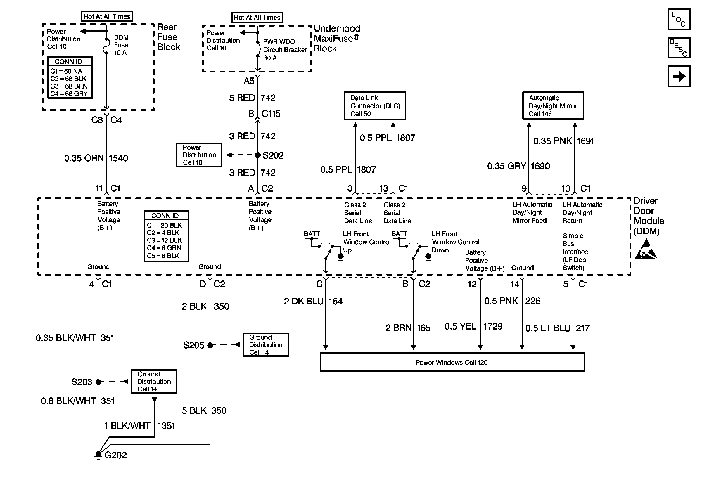
Refer to
Cell 55

Circuit Description
The battery positive voltage (B+) is supplied to the driver door module (DDM) at the DDM connector C1 terminal 11, CKT 1540 (ORN). The DDM monitors this voltage to determine if the voltage is within a valid operating range.
Conditions for Setting the DTC
The battery positive voltage (B+) exceeds 15.5 V for more than 1 second.
Action Taken When the DTC Sets
| • | DTC B1982 is stored in the DDM memory. |
| • | The DDM will not respond to any manual or memory inputs when the voltage is greater than 16 V. |
| • | No driver warning message is displayed for this DTC. |
| • | The DDM switch failure and position sensor failure DTCs will not set while DTC B1982 is current. |
Conditions for Clearing the DTC
| • | The B+ voltage falls below 15 volts for approximately 1.2 seconds. |
| • | The history DTC will clear after 50 ignition cycles. |
| • | Use a scan tool in order to clear the history DTC. |
Diagnostic Aids
This DTC may set when the vehicle is placed on a battery charger set to FAST CHARGE for a long period of time.
Test Description
The number(s) below refer to the step number(s) on the diagnostic table.
-
Perform the power door diagnostic system check before diagnosing DTC B1982.
-
This verifies that the DTC was not incorrectly set.
-
This determines whether the malfunction is in the charging system or the driver door module (DDM).
-
Clear any DTCs after completing the repair procedure.
Step | Action | Value(s) | Yes | No |
|---|---|---|---|---|
Did you perform the Power Door Diagnostic System Check? | -- | Go to Step 2 | ||
Is the B+ voltage less than the specified value? | 15.5 V | Go to Step 4 | Go to Step 3 | |
Is the voltage greater than the specified value? | 15.5 V | Refer to Charging System Check | Go to Step 4 | |
4 | Replace the DDM. Refer to Front Door Module Replacement . Did you complete the repair? | -- | Go to Step 5 | -- |
Did you clear all of the DTCs? | -- | -- |
