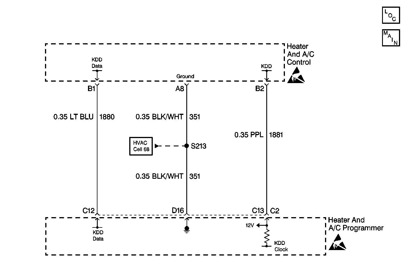
Circuit Description
The A/C control assembly receives voltage signals from the heater control module. The signal voltage will vary from 5 volts (open circuit) to 0 volts (short circuit).
Conditions for Setting the DTC
| • | The ignition is ON. |
| • | The circuit is open or shorted. |
Action Taken When the DTC Sets
| • | Code B1399 is set. |
| • | The A/C control will not operate. |
Conditions for Clearing the DTC
| • | Using a Scan Tool . |
| • | A history DTC will clear after 50 fault free ignition cycles. |
| • | HCM battery voltage is interrupted. |
-
Perform the Body Control Module Diagnostic System Check before continuing with the diagnosis of this DTC.
-
Determines if the programmer or A/C control is malfunctioning.
-
Determines whether the programmer is malfunctioning or if there is an open/short in the circuit.
Step | Action | Value(s) | Yes | No |
|---|---|---|---|---|
Did you perform the BCM diagnostic system check? | -- | Go to Step 2 | ||
2 |
Refer to Measuring Voltage in Wiring Systems. Does the voltage equal the specified value? | 4.5V | Go to Step 3 | Go to Step 7 |
Measure the voltage at heater and A/C control assembly connector terminals B1 and A8. Refer to Measuring Voltage in Wiring Systems. Does the voltage equal the specified value? | 3.5V | Go to Step 6 | Go to Step 4 | |
Backprobe the heater and A/C control assembly harness connector to measure the voltage at terminals C13 and D16. Refer to Probing Electrical Connectors and Measuring Voltage in Wiring Systems. Does the voltage equal the specified value? | 1.0V | Go to Step 8 | Go to Step 5 | |
5 |
Did you replace the heater and A/C programmer? | -- | -- | |
6 |
Did you replace the heater and A/C control assembly? | -- | -- | |
7 | Backprobe the HCM harness connector at terminal C12 and terminal D16. Refer to Probing Electrical Connectors and Measuring Voltage in Wiring Systems. Does the voltage equal the specified value? | 4.5V | Go to Step 9 | Go to Step 5 |
8 | Repair the open in CKT 1180 (PPL). Refer to Wiring Repairs in Wiring Systems. Is the repair complete? | -- | -- | |
9 | Repair the open in CKT 1181 (LT BLU). Refer to Wiring Repairs in Wiring Systems. Is the repair complete? | -- | -- |
