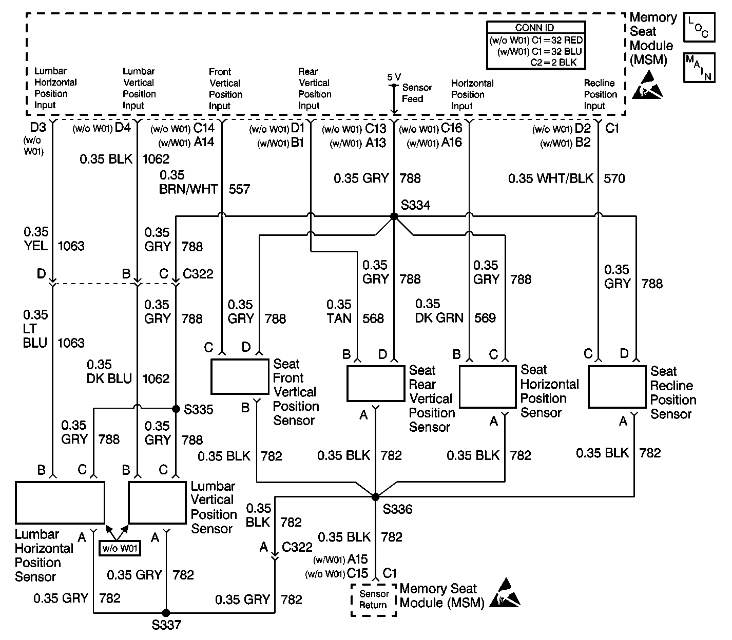
Circuit Description
The memory seat module (MSM) receives inputs from the lumbar position sensors during memory recall and memory set functions. The potentiometers in the position sensors vary in resistance as the motors move the lumbar support. The MSM receives a variable voltage input depending on the resistance of the potentiometer. During memory set, the MSM records the voltage across the lumbar potentiometers. During memory recall, the MSM moves the lumbar motors until the voltage across each potentiometer matches the voltages stored. During normal operation, the lumbar position sensors are tested against the out-of-range limits.
Conditions for Setting the DTC
| • | These DTCs set only if DTC MSM B1982 or DTC MSM B1983 is not current. For the diagnosis of these DTCs, refer to DTC B1982 Source/Battery Voltage High or DTC B1983 Source/Battery Voltage Low . |
| • | The MSM sets the appropriate DTC whenever the MSM detects that the sensor input voltage is not within 0.25-4.75 volts. |
Action Taken When the DTC Sets
When a position sensor DTC is set as current, the MSM disables the affected motor during the memory recall operation. The motor remains enabled for manual positioning.
Conditions for Clearing the DTC
The MSM does not detect the position sensor failure during the last monitoring cycle.
Test Description
The number(s) below refer to the step number(s) on the diagnostic table.
Step | Action | Value(s) | Yes | No |
|---|---|---|---|---|
Did you perform the Power Seat Systems Diagnostic System Check? | -- | Go to Step 2 | ||
2 |
Is the voltage within the specified range? | 4.6-5.2 V | Go to Step 3 | Go to Step 5 |
3 | Test for an open or a short in CKT 1063 (YEL) or (LT BLU). Refer to Testing for Continuity in Wiring Systems. Is CKT 1063 OK? | -- | Go to Step 4 | Go to Step 10 |
4 | Replace the horizontal lumbar motor assembly. Did you complete the repair? | -- | Go to Step 11 | -- |
5 | Test for an open in CKT 788 (GRY) between the position sensor and S334. Refer to Testing for Continuity in Wiring Systems. Is CKT 788 OK? | -- | Go to Step 6 | Go to Step 10 |
6 | Test for an open in CKT 782 (BLK) or (GRY) between the position sensor and S336. Refer to Testing for Continuity in Wiring Systems. Is CKT 782 OK? | -- | Go to Step 7 | Go to Step 10 |
7 | Test for proper terminal contact at the MSM connector C1 cavity C15 (BLK) and cavity C13 (GRY). Refer to Intermittents and Poor Connections Diagnosis in Wiring Systems. Is the terminal contact OK? | -- | Go to Step 9 | Go to Step 8 |
8 | Repair the poor contact in cavity C13 (GRY) or cavity C15 (BLK). Refer to Repairing Connector Terminals in Wiring Systems. Did you complete the repair? | -- | Go to Step 11 | -- |
9 | Replace the MSM. Refer to Memory Seat Control Module Replacement in Seats. Did you complete the repair? | -- | Go to Step 11 | -- |
10 | Repair the suspect wiring Refer to Wiring Repairs in Wiring Systems. Did you complete the repair? | -- | Go to Step 11 | -- |
11 | Clear the DTCs from memory. Did you clear the DTCs? | -- | -- |
