Removal Procedure
- Remove the booster vacuum hose from the vacuum check valve.
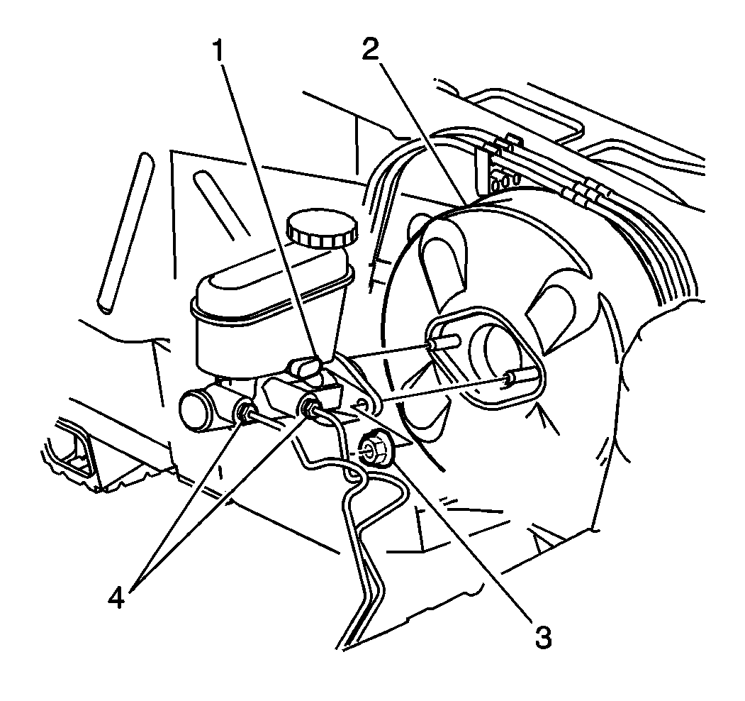
- Remove the master cylinder attaching nuts (3).
- Disconnect the master cylinder (1) from the booster (2).
- Move the master cylinder forward just enough to clear the studs on the booster. This will flex the brake pipes slightly. Do not bend or distort the pipes.
- Remove the left closeout panel. Refer to Instrument Panel Insulator Panel Replacement - Left Side in Instrument Panel, Gauges, and Panel.
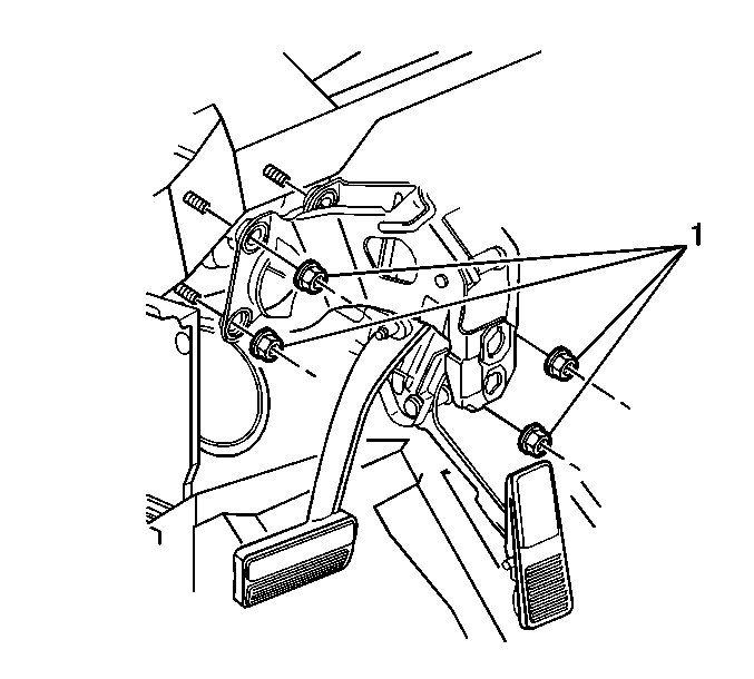
- Remove the booster attaching nuts (1).
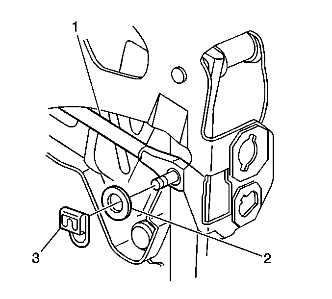
- Remove the pushrod retainer (3) and the washer (2) from the push rod clevis pin.
- Remove the pushrod off of the pedal clevis pin without putting undue side pressure on the pushrod.
- Remove the booster from the vehicle.
- Remove the gasket.
Important: The booster can be removed from the vehicle without removing or disconnecting the master cylinder. However, if both the booster and the master cylinder are to be removed, remove the master cylinder first. Refer to Master Cylinder Replacement

Installation Procedure
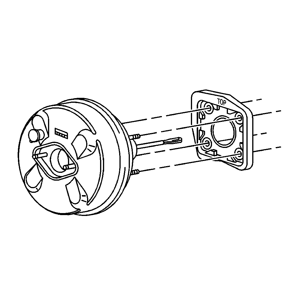
- Connect the gasket to the booster.
- Install the booster to the vehicle.
- Without putting undue side pressure on the pushrod (1) Install the booster pushrod (1) to the brake pedal clevis pin.
- Install the pushrod washer (2) and retainer (3) to the push rod clevis pin.
- Install the booster attaching nuts (1).
- Install the left closeout panel. Refer to Instrument Panel Insulator Panel Replacement - Left Side in Instrument Panel, Gauges, and Panel.
- Install the master cylinder (1) to the booster (2). Refer to Master Cylinder Replacement .
- Install the booster vacuum hose to the vacuum check valve.
Notice: Use the correct fastener in the correct location. Replacement fasteners must be the correct part number for that application. Fasteners requiring replacement or fasteners requiring the use of thread locking compound or sealant are identified in the service procedure. Do not use paints, lubricants, or corrosion inhibitors on fasteners or fastener joint surfaces unless specified. These coatings affect fastener torque and joint clamping force and may damage the fastener. Use the correct tightening sequence and specifications when installing fasteners in order to avoid damage to parts and systems.
Tighten
Tighten the attaching nuts to 23 N·m (17 lb ft).
