Tools Required
J 36850
Transjel
Removal Procedure
Caution: Unless directed otherwise, the ignition and start switch must be in the OFF or LOCK position, and all electrical loads must be OFF before servicing
any electrical component. Disconnect the negative battery cable to prevent an electrical spark should a tool or equipment come in contact with an exposed electrical terminal. Failure to follow these precautions may result in personal injury and/or damage to
the vehicle or its components.
- Disconnect the negative battery cable.
- Remove the case side cover. Refer to
Control Valve Body Cover Replacement
.
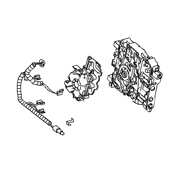
- Remove the wiring harness as necessary.
- Remove the oil pump. Refer to
Oil Pump Replacement
.
- Remove the valve body to channel plate
bolts.
- Remove the valve body. Leave the spacer plate with the
transmission.
- Remove the spacer plate and the spacer
plate gasket, as necessary.
- Remove the solenoid screens.
Installation Procedure
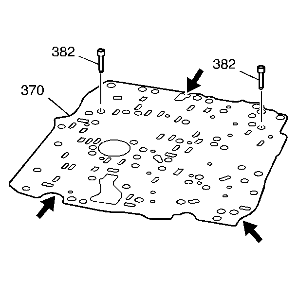
- Inspect the control valve body spacer plate (370) for the following conditions:
| • | Damaged gasket sealing surfaces |
| • | Plugged or damaged screen/seal assemblies (382) |
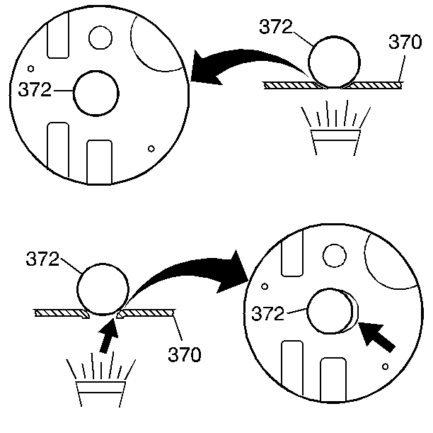
- Inspect each ball check valve seat (one at a time) on the spacer plate (370) for excessive peening.
| • | Place a ball check valve (372) on each seat |
| • | Use a flashlight to look for visible light between the ball check valve and the seat. |
| • | If light is visible between the ball check valve and the seat, replace the spacer plate assembly (370). |
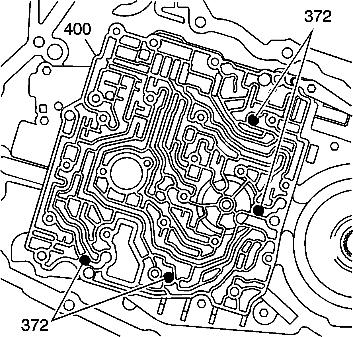
- Install four ball check valves (372) into the case cover (400), in the positions shown. Use
J 36850
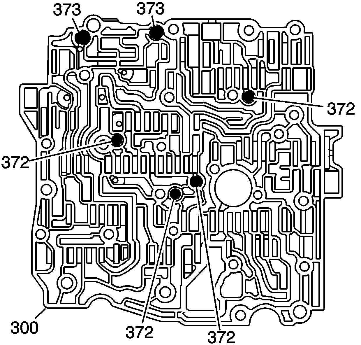
- Install the two larger ball check valves (373) and the four smaller ball check valves (372) into the control valve body (300).
Use
J 36850
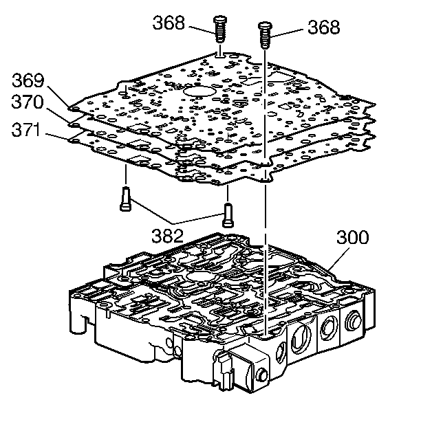
- Install the screen/seal assemblies (382) into the spacer plate assembly (370).
- Install the control valve body to spacer plate gasket (371), the spacer plate assembly (370) and the case cover to spacer plate gasket (369) onto the control valve body (300).
- Install the bolts (368) to hold the spacer plate and gaskets onto the control valve body (300).
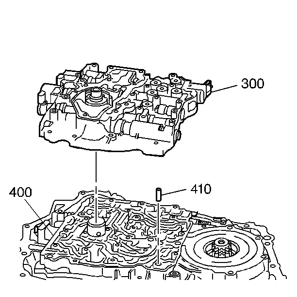
- Install the control valve body alignment sleeve (410) into the case cover (400).
Important:
| • | Use the control valve body alignment sleeve (410) and turbine shaft sleeve in the case cover (400) as guides. |
| • | Be sure that the ball check valves do not drop out of the control valve body (300) during assembly. |
- Install the control valve body (300) onto the case cover (400).
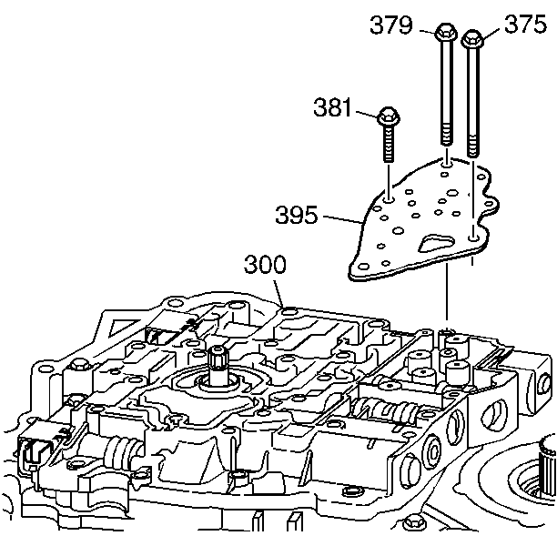
- Install the transmission fluid pressure (TFP) manual valve position switch assembly (395) onto the control valve body (300).
Important: Finger start the bolts to prevent cross-threading.
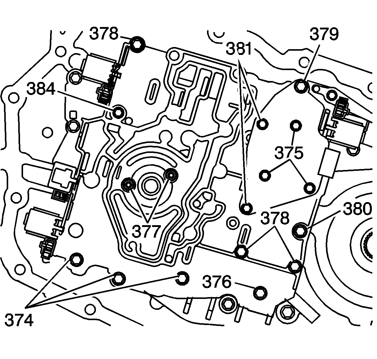
- Install the control valve body bolts (374-381, 384) as indicated.
Important:
| • | Tighten the bolts in a spiral pattern starting with the bolts at the center of the control valve body. |
| • | If the bolts are tightened at random, valve bores may become distorted and inhibit proper valve operation. |
Notice: Use the correct fastener in the correct location. Replacement fasteners
must be the correct part number for that application. Fasteners requiring
replacement or fasteners requiring the use of thread locking compound or sealant
are identified in the service procedure. Do not use paints, lubricants, or
corrosion inhibitors on fasteners or fastener joint surfaces unless specified.
These coatings affect fastener torque and joint clamping force and may damage
the fastener. Use the correct tightening sequence and specifications when
installing fasteners in order to avoid damage to parts and systems.
- Tighten the control valve body bolts (374-381, 384) as indicated by the following list.
Tighten
| • | 374 - 12 N·m (106 lb in) |
| • | 375 - 12 N·m (106 lb in) |
| • | 376 - 12 N·m (106 lb in) |
| • | 377 - 12 N·m (106 lb in) |
| • | 378 - 12 N·m (106 lb in) |
| • | 379 - 16 N·m (11 lb ft) |
| • | 380 - 25 N·m (18 lb ft) |
| • | 384 - 12 N·m (106 lb in) |
- Install the oil pump. Refer to
Oil Pump Replacement
.
- Install the wiring harness.
- Install the case side cover. Refer to
Control Valve Body Cover Replacement
.
- Connect the negative battery cable.
- Adjust the oil level.
Important: It is recommended that transmission adaptive pressure (TAP) information be reset.
Resetting the TAP values using a scan tool will erase all learned values in all cells. As a result, The ECM, PCM or TCM will
need to relearn TAP values. Transmission performance may be affected as new TAP values are learned.
- Reset the TAP values. Refer to
Adapt Function
.
