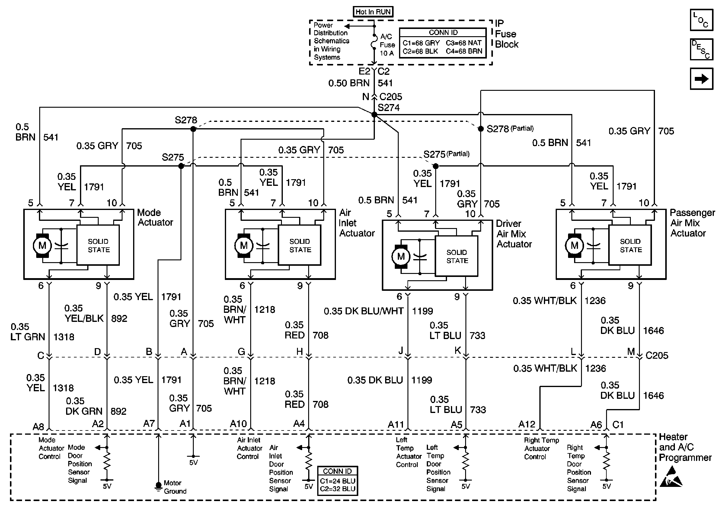
Step | Action | Value(s) | Yes | No |
|---|---|---|---|---|
Schematic Reference HVAC
AIR Delivery/Temperature Control Schematics
| ||||
1 | Did you perform the Air Delivery and Temperature Control Check? | -- | Go to Step 2 | |
2 |
Does the voltage measure near the specified value? | B+ | Go to Step 3 | Go to Step 4 |
3 |
Did you find and correct the condition? | -- | Go to Step 13 | Go to Step 5 |
4 | Test the ignition positive voltage circuit of the HTR/DEF/AC door motor for an open or a short to ground. Refer to Circuit Testing and Wiring Repairs in Wiring Systems. Did you find and correct the condition? | -- | Go to Step 13 | Go to Step 7 |
5 |
Does the drive shaft of the HTR/DEF/AC door motor rotate and do the counts change? | -- | Go to Step 6 | Go to Step 10 |
6 |
Does the voltage measure near the specified value when airflow moves toward AC, near the specified value when airflow moves toward DEF, and near the specified value when stationary? | 5 V toward A/C 0 V toward DEF 2.5 V stationary | Go to Step 7 | Go to Step 9 |
7 |
Did you find and correct the condition? | -- | Go to Step 13 | Go to Step 8 |
8 | Replace the HVAC module. Refer to HVAC Module Assembly Replacement in Heating and Ventilation. Did you complete the replacement? | -- | Go to Step 13 | -- |
9 | Inspect for poor connections at the harness connector of the heater and A/C programmer. Refer to Testing for Intermittent Conditions and Poor Connections and Connector Repairs in Wiring Systems. Did you find and correct the condition? | -- | Go to Step 13 | Go to Step 11 |
10 | Inspect for poor connections at the harness connector of the HTR/DEF/AC door motor . Refer to Testing for Intermittent Conditions and Poor Connections and Connector Repairs in Wiring Systems. Did you find and correct the condition? | -- | Go to Step 13 | Go to Step 12 |
11 | Replace the heater and A/C programmer. Refer to Programmer Replacement . Did you complete the replacement? | -- | Go to Step 13 | -- |
12 | Replace the HTR/DEF/AC door motor. Refer to Mode Actuator Replacement . Did you complete the replacement? | -- | Go to Step 13 | -- |
13 | Operate the system in order to verify the repair. Did you correct the condition? | -- | System OK | Go to Step 2 |

