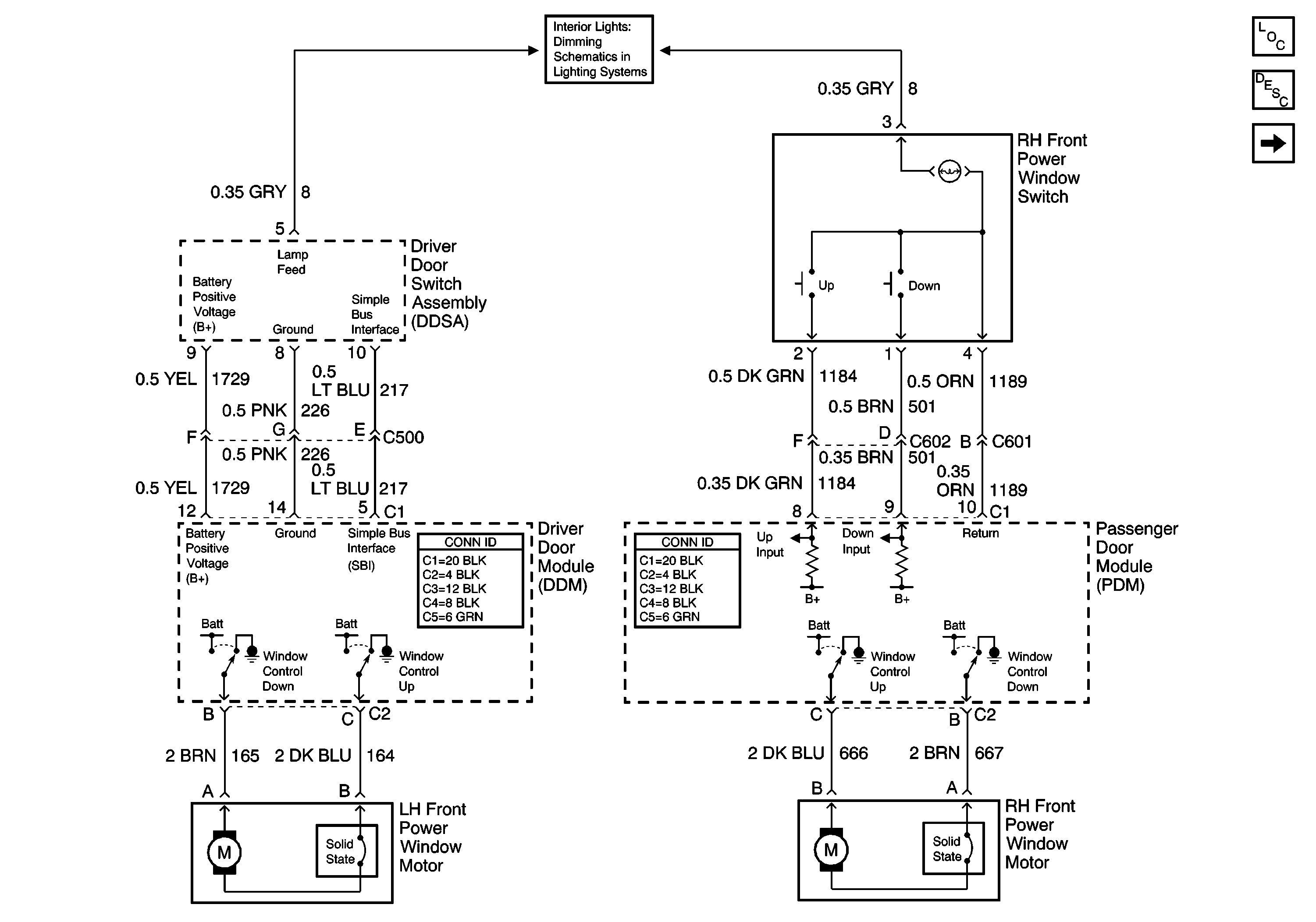
Schematic
Refer to Power Window Schematics
Front Power Window Components

.
Circuit Description
The simple bus interface provides a communications path from the LH front power window switch to the driver door module (DDM). The DDM contains the following two types of software:
| • | Switch message decoding software |
| • | Simple bus interface diagnostic software |
The software enables the DDM to monitor the state of the LH front power window switch.
Conditions for Running the DTC
| • | All modules involved in the circuit must be powered |
| • | No module involved in the circuit may have B1982 (battery voltage high) or B1983 (battery voltage low) set as a current DTC. |
| • | All modules involved in the circuit must be communicating (no current communication DTC set). |
Conditions for Setting the DTC
DTC B2212 will set any time the driver door power window switch for the UP direction of the right front window is continuously closed for a period greater than 15 seconds.
DTCs B1982 (battery Voltage High) and B1983 (Battery Voltage Low) must not be current or the diagnostic will not run.
Action Taken When the DTC Sets
The switch command will be ignored until it again changes state.
Conditions for Clearing the DTC
| • | This DTC will be set from current to history when the window UP input cycles off. |
| • | The history DTC will clear after 50 ignition cycles. |
Diagnostic Aids
| • | A history DTC is evidence of an intermittent problem. |
| • | If DTC B2212 is current, cycle the ignition switch from OFF to RUN. If this DTC is still current, perform the following diagnostics. |
Test Description
The number(s) below refer to the step number(s) on the diagnostic table.
-
Check the module input state using the normal input status.
-
Check to see that the input is seen by the module.
Step | Action | Yes | No |
|---|---|---|---|
1 | Did you perform A Diagnostic System Check - Door Systems? | Go to Step 2 | |
Does the scan tool display Idle? | Go to Step 3 | Go to Step 4 | |
Does the door window switch parameter change state? | Go to Diagnostic Aids | Go to Step 4 | |
4 | Inspect for poor connections/terminal tension at the driver door window switch harness connector. Refer to Testing for Intermittent Conditions and Poor Connections and Connector Repairs in Wiring Systems. Did you find and correct the condition? | Go to Step 6 | Go to Step 5 |
5 | Replace the driver door window switch. Refer to Front Door Switch Replacement . Did you complete the replacement? | Go to Step 6 | -- |
6 |
Does the DTC reset? | Go to Step 2 | System OK |
