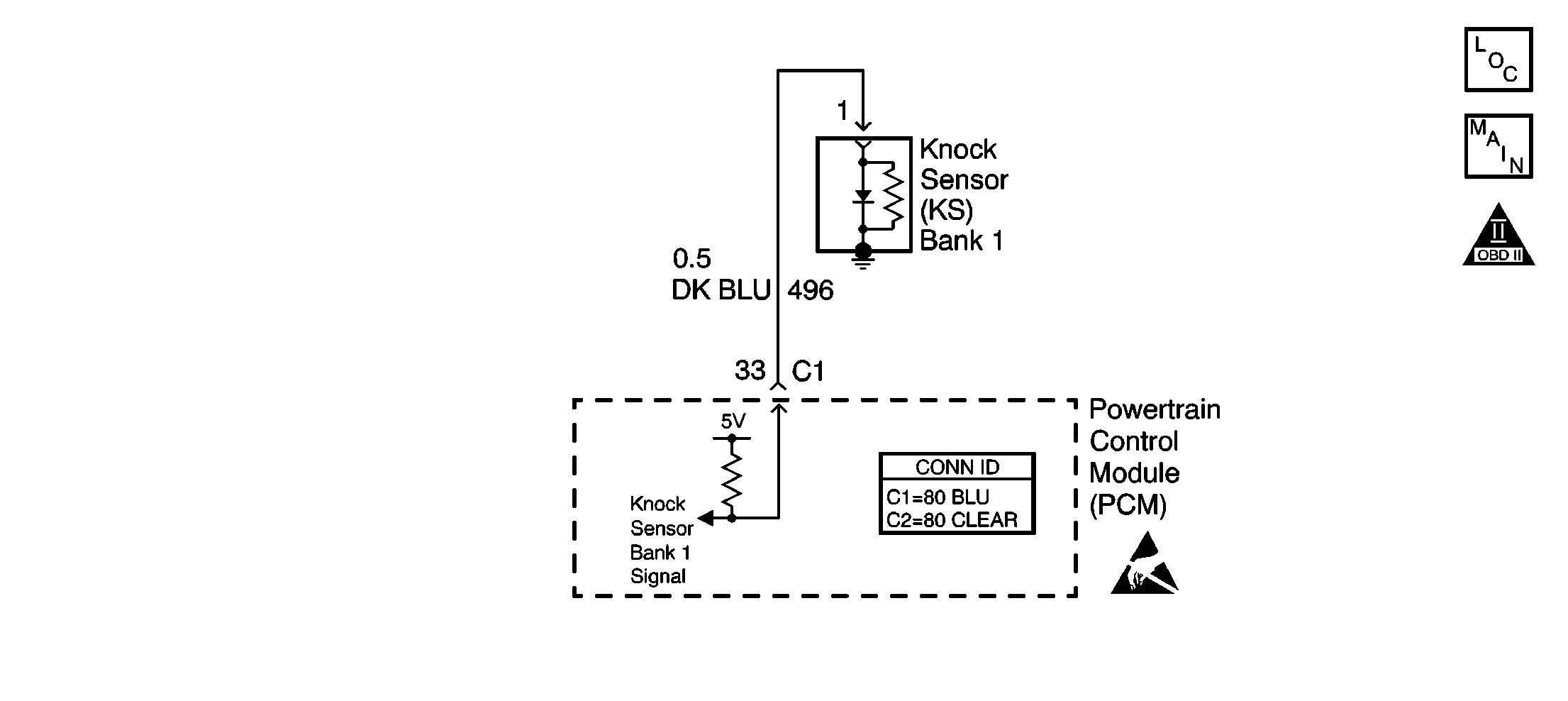
Circuit Description
The PCM contains integrated knock sensor (KS) diagnostic circuitry. Input signals from the knock sensors are used to detect engine detonation, allowing the PCM to retard ignition control (IC) spark timing based on the amplitude and frequency of the KS signal being received. The knock sensors produce an AC signal under all engine operating conditions. During engine operation, the PCM calculates the average voltage of each knock sensors signal. If the knock sensor system is operating normally, the PCM should monitor KS signal voltages varying over 0.5 volt above and below the calculated average voltage. If the PCM detects a knock sensor 1 signal voltage within the calculated average voltage range, DTC P0327 will set.
Conditions for Running the DTC
| • | No TP sensor, VSS, CKP, MAF, or ECT DTCs are set |
| • | VIN K - Engine speed is between 1000-4000 rpm. |
| • | VIN 1 - Engine speed is between 1000-3000 rpm. |
| • | VIN K - Throttle angle is more than 3 percent. |
| • | VIN 1 - Throttle angle is more than 15 percent. |
| • | VIN K - Engine load is more than 20 percent. |
| • | VIN 1 - Engine load is more than 45 percent. |
| • | Engine coolant temperature is more than 75°C (167°F). |
| • | Maximum spark retard is less than 15 degrees. |
| • | System voltage is more than 9 volts. |
Conditions for Setting the DTC
The PCM detects a knock sensor 1 signal voltage within the calculated average voltage range.
Action Taken When the DTC Sets
The PCM stores conditions which were present when the DTC set as Failure Records only. This information will not be stored as Freeze Frame Records.
Conditions for Clearing the MIL/DTC
| • | The DTC becomes history when the conditions for setting the DTC are no longer present. |
| • | The history DTC clears after 40 malfunction free warm-up cycles. |
| • | The PCM receives a clear code command from the scan tool. |
Diagnostic Aids
Check for the following conditions:
| • | Poor connection at the PCM or knock sensor 1. |
| Inspect knock sensor 1 and PCM connectors for backed out terminals, broken locks, and improperly formed or damaged terminals. |
| • | Misrouted harness. |
| Inspect the knock sensor harness to ensure that it is not routed too close to high voltage wires such as spark plug leads. |
Reviewing the Failure Records vehicle mileage since the diagnostic test last failed may help determine how often the condition that caused the DTC to be set occurs. This may assist in diagnosing the condition.
Test Description
The numbers below refer to the step numbers on the diagnoatic table.
-
Ensures that the malfunction is present.
-
If sent here from symptoms, proceed with the diagnostic table.
Step | Action | Values | Yes | No |
|---|---|---|---|---|
1 | Did you perform the Powertrain On-Board Diagnostic (OBD) System Check ? | -- | ||
|
Important: If a mechanical engine knock can be heard, repair the engine mechanical problem before proceeding with this diagnostic. Refer to Engine Noise Diagnosis in Engine Mechanical.
Does scan tool indicate DTC P0327 failed this ignition? | -- | |||
Does the scan tool indicate DTC P0327 failed this ignition? | -- | Go to Diagnostic Aids | ||
4 |
Was problem found? | 0V | ||
5 |
Was problem found? | -- | ||
6 | Replace the knock sensor. Refer to Knock Sensor Replacement - Bank 1 or Knock Sensor Replacement - Bank 2 . Is action complete? | -- | -- | |
7 |
Does the scan tool indicate DTC P0327 failed this ignition? | -- | System OK |
