Refer to Engine Controls Schematics
Fuel Contol, L36
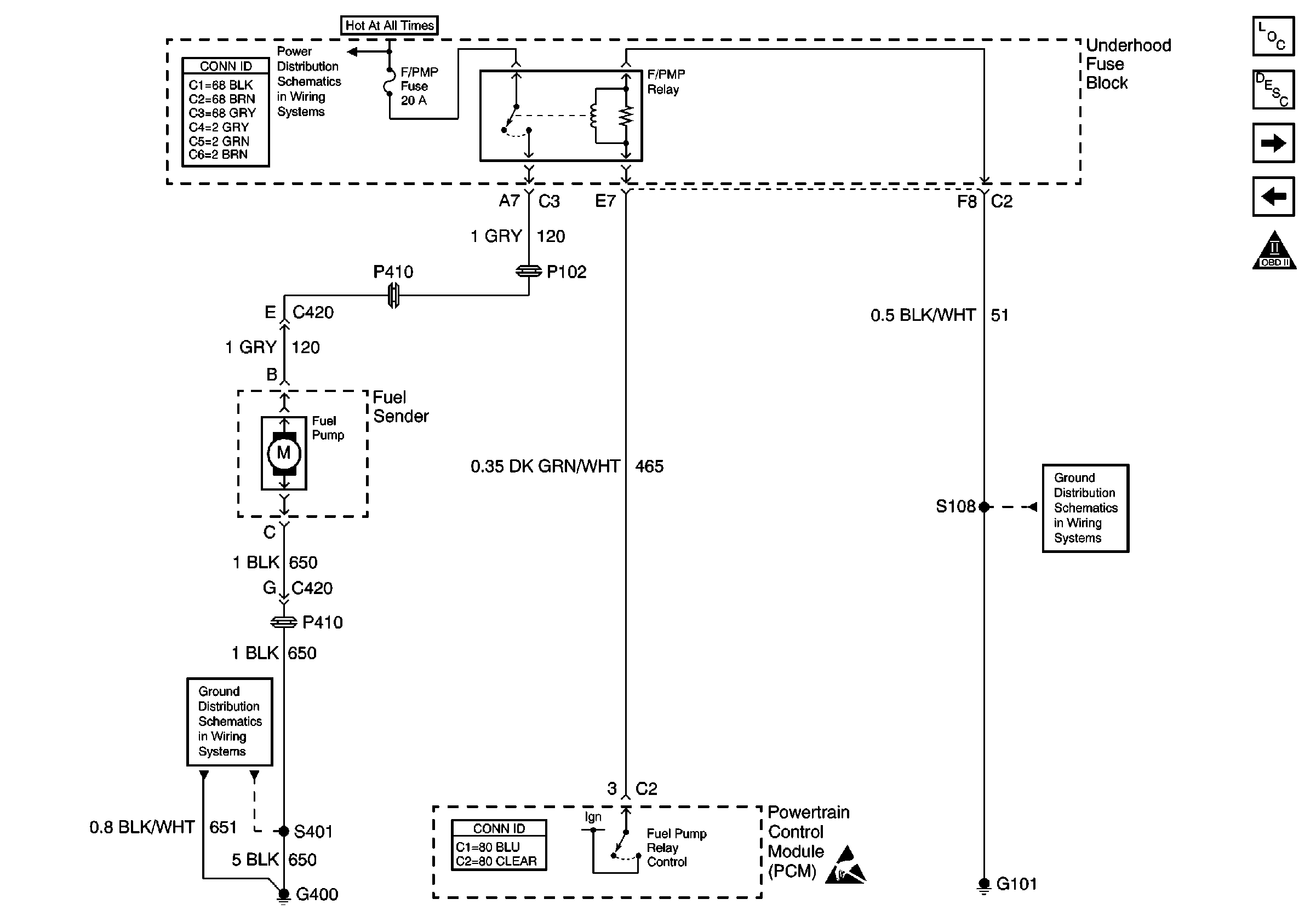
or
Fuel Contol, L67
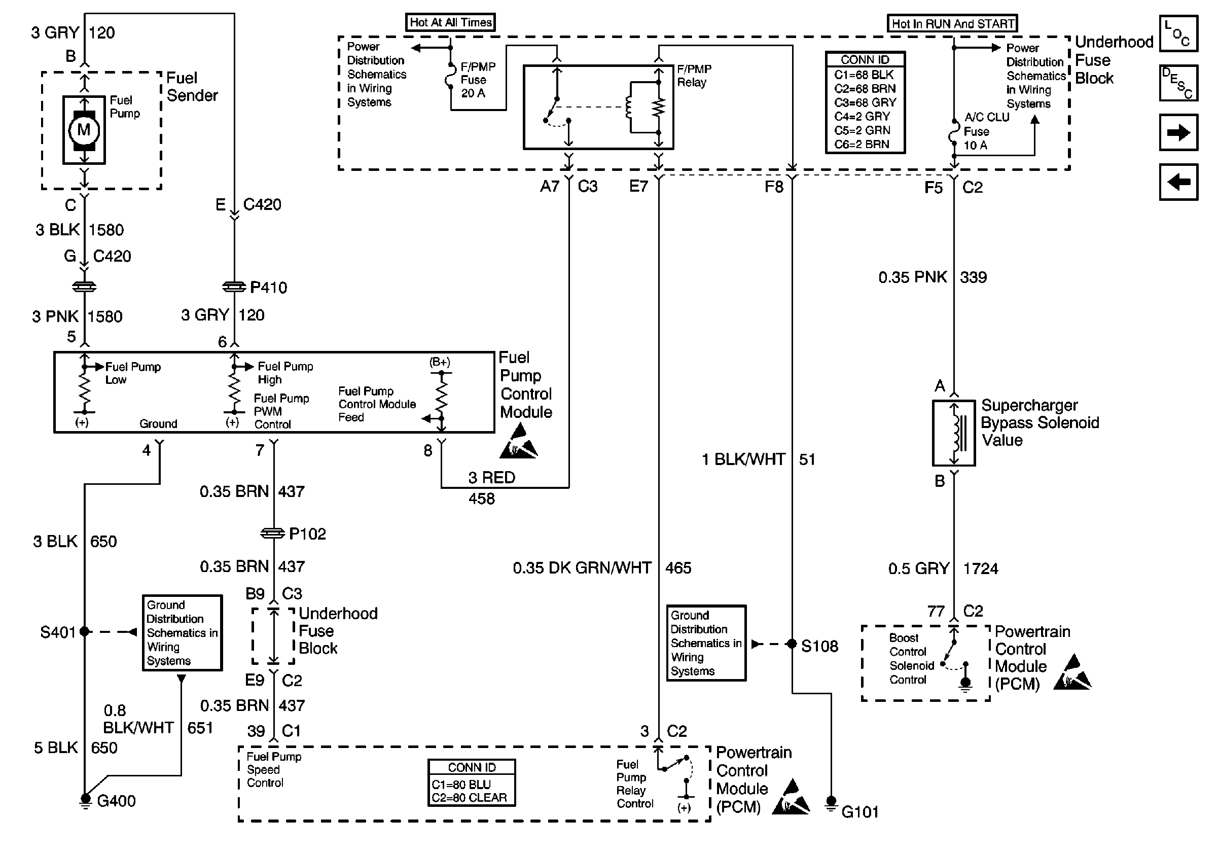
for a wiring diagram.
Circuit Description
The PCM provides ignition positive voltage to control the fuel pump relay. The PCM has the ability to detect an electrical malfunction on the relay control circuit. When the ignition is first turned ON, the PCM energizes the fuel pump relay which applies power to the fuel pump. The fuel pump relay will remain ON as long as the engine is running or cranking and the PCM is receiving reference pulses. If no reference pulses are present, the PCM de-energizes the fuel pump relay within 2 seconds after the ignition is turned ON or the engine is stopped. With the engine stopped, the fuel pump can be turned ON by using the scan tool output controls function. If an electrical malfunction is detected, the PCM will set DTC P0230.
Conditions for Running the DTC
The ignition is ON.
Conditions for Setting the DTC
| • | The PCM detects an electrical malfunction on the fuel pump relay control circuit. |
| • | The condition is present for 0.5 second. |
Action Taken When the DTC Sets
The PCM stores conditions which were present when the DTC set as Failure Records only. This information will not be stored as Freeze Frame Records.
Conditions for Clearing the MIL/DTC
| • | The DTC becomes history when the conditions for setting the DTC are no longer present. |
| • | The history DTC clears after 40 malfunction free warm-up cycles. |
| • | The PCM receives a clear code command from the scan tool. |
Diagnostic Aids
An intermittent may be caused by a poor connection, rubbed through the wire insulation or a wire broken inside of the insulation.
Check for the following conditions:
| • | Poor connections at the PCM or fuel pump relay. |
| Inspect harness connectors for backed out terminals, improper mating, broken locks, improperly formed or damaged terminals, and poor terminal to wire connection. Use a corresponding mating terminal to test for proper terminal tension. |
| • | Damaged harness |
| Inspect the wiring harness for damage. |
Reviewing the Failure Records vehicle mileage since the diagnostic test last failed may help determine how often the condition that caused the DTC to be set occurs. This may assist in diagnosing the condition.
Test Description
The numbers below refer to the step numbers on the diagnostic table.
-
Listen for an audible click when the relay operates. Command both the ON and OFF states. Repeat the commands as necessary.
-
Verifies that the PCM is providing voltage to the relay.
-
Tests for an open in the ground circuit to the relay.
-
Tests if voltage is constantly being applied to the relay.
-
The PCM utilizes Electrically Erasable Programmable Read Only Memory (EEPROM). When the PCM is replaced, the new PCM must be programmed.
Step | Action | Values | Yes | No |
|---|---|---|---|---|
1 | Did you perform the Powertrain On-Board Diagnostic (OBD) System Check? | -- | Go to Step 2 | |
Does the relay turn ON and OFF with each command? | -- | Go to Diagnostic Aids | Go to Step 3 | |
Does the test lamp turn ON and OFF with each command? | -- | Go to Step 4 | Go to Step 5 | |
Does the test lamp turn ON and OFF with each command? | -- | Go to Step 8 | Go to Step 10 | |
Does the test lamp remain illuminated with each command? | -- | Go to Step 7 | Go to Step 6 | |
6 | Test the control circuit of the relay for a short to ground or an open. Refer to Wiring Repairs in Wiring Systems. Did you find and correct the condition? | -- | Go to Step 13 | Go to Step 9 |
7 | Test the control circuit of the relay for a short to voltage. Refer to Wiring Repairs in Wiring Systems. Did you find and correct the condition? | -- | Go to Step 13 | Go to Step 9 |
8 | Inspect for poor connections at the relay. Refer to Testing for Intermittent Conditions and Poor Connections and Connector Repairs in Wiring systems. Did you find and correct the condition? | -- | Go to Step 13 | Go to Step 11 |
9 | Inspect for poor connections at the PCM. Refer to Testing for Intermittent Conditions and Poor Connections and Connector Repairs in Wiring Systems. Did you find and correct the condition? | -- | Go to Step 13 | Go to Step 12 |
10 | Repair the ground circuit of the relay. Refer to Wiring Repairs in Wiring Systems. Did you complete the repair? | -- | Go to Step 13 | -- |
11 | Replace the relay. Did you complete the replacement? | -- | Go to Step 13 | -- |
|
Important: Perform the set up procedure for the PCM. Replace the PCM. Refer to Powertrain Control Module Replacement/Programming . Did you complete the replacement? | -- | Go to Step 13 | -- | |
13 |
Does the DTC reset? | -- | Go to Step 2 | System OK |
