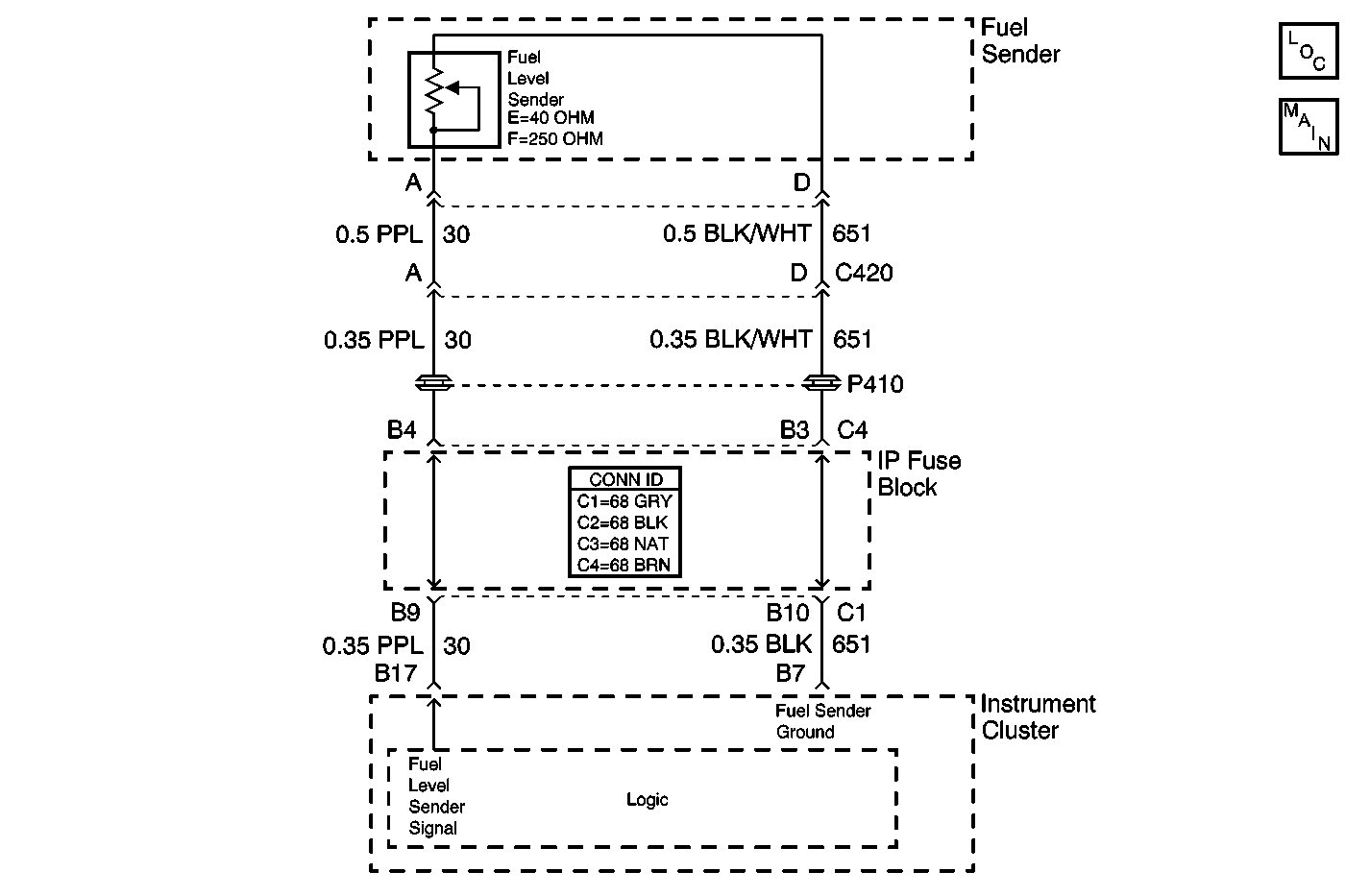
Circuit Description
The instrument cluster monitors the fuel level directly from the fuel level sensor on a discrete input. The fuel level sensor has a resistance range from 40 ohms (below E) to 250 ohms (above F). The instrument cluster filters the raw fuel level data in order to display the data on the gauge. The instrument cluster has two filter modes.
One filter mode is a slow (heavy) filter. The vehicle uses the slow filter when the vehicle is not in PARK . The slow filter prevents fuel slosh from affecting the fuel gauge display.
The second filter mode is a fast (light) filter. The vehicle uses the fast filter when the vehicle is in PARK. The fast filter allows the fuel gauge display to respond quickly whenever the vehicle is refueling.
The instrument cluster also sends raw fuel level data to the PCM through the class 2 serial data line.
Conditions for Running the DTC
The IPC must be active. DTCs B0532 or B0533 are not logged as current.
Conditions for Setting the DTC
DTC B0530 sets when the instrument cluster detects that the fuel level sensor has not moved up or down one liter for 100 miles.
Action Taken when DTC Sets
When the DTC B0530 sets, the following events occur:
| • | The instrument cluster moves the fuel gauge pointer to the lowest position below E. |
| • | The instrument cluster does not illuminate the low fuel LED indicator. |
| • | The instrument cluster sends a class 2 message to the PCM indicating the condition. |
Conditions for Clearing the DTC
The IPC detects that the filtered fuel level input has fluctuated at least one liter since the value it failed at.
Diagnostic Aids
The IPC will store the code as current only as long as the failure exists. An intermittent failure will be stored as a history DTC.
Test Description
The numbers below refer to the step numbers on the diagnostic table.
Step | Action | Value(s) | Yes | No |
|---|---|---|---|---|
1 | Did you perform the Instrument Cluster Diagnostic System Check? | -- | Go to Step 2 | |
Is the fuel level indicator below the (E) empty mark on the gauge? | -- | Go to Step 3 | Go to Testing for Intermittent Conditions and Poor Connections in Wiring Systems | |
3 |
Does the fuel gauge display E at 40 ohms and display F at 250 ohms? | 40 ohms Empty 250 ohms Full | Go to Step 4 | Go to Step 5 |
4 | Replace the fuel level sensor. Refer to Fuel Level Sensor Replacement in Engine Controls-3.8L. Did you complete the replacement? | -- | Go to Step 6 | -- |
5 | Replace the instrument panel cluster. Refer to Instrument Cluster Replacement . Did you complete the replacement? | -- | Go to Step 6 | -- |
6 |
Does the DTC reset? | -- | System OK | Go to Step 2 |
