Tools Required
J 42640 Steering Column Lock Pin
Removal Procedure
- Disable the SIR system. Refer to Disabling the SIR System in SIR.
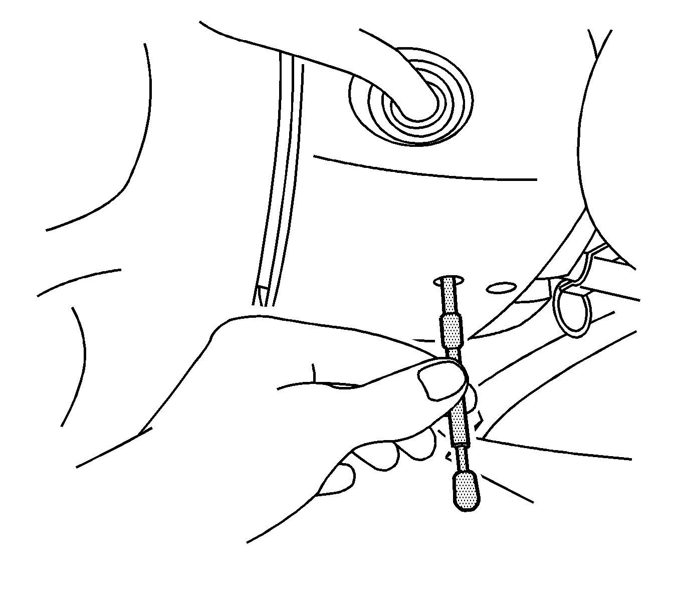
- Insert J 42640 into the steering column access hole in order to lock the steering column. This will maintain the correct orientation.
- Raise and support the vehicle. Refer to Lifting and Jacking the Vehicle in General Information.
- Remove the left front tire from the vehicle. Refer to Tire and Wheel Removal and Installation in Tires and Wheels.
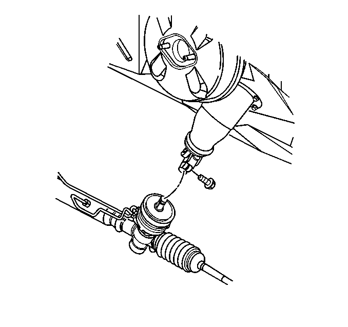
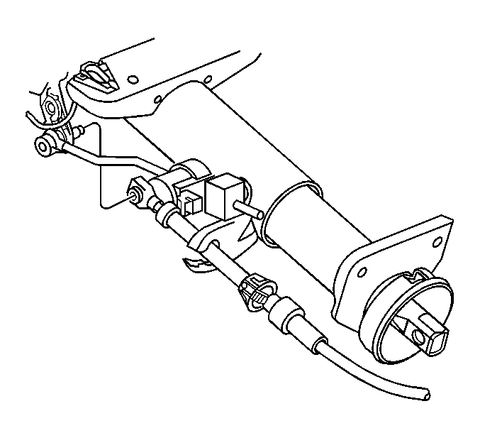
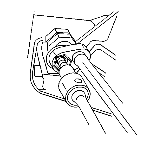
- Remove the lower pinch bolt from the intermediate shaft.
- Remove the intermediate shaft from the steering gear stub shaft.
- Lower the vehicle.
- Remove the I/P trim panel. Refer to Instrument Panel Lower Trim Panel Replacement in Instrument Panel, Gauges, and Console.
- Disconnect the shift lever cable from the linear shift assembly.
- Remove the shift cable retaining clip.
- Pinch the retaining clips together and remove the shift cable from the steering column.
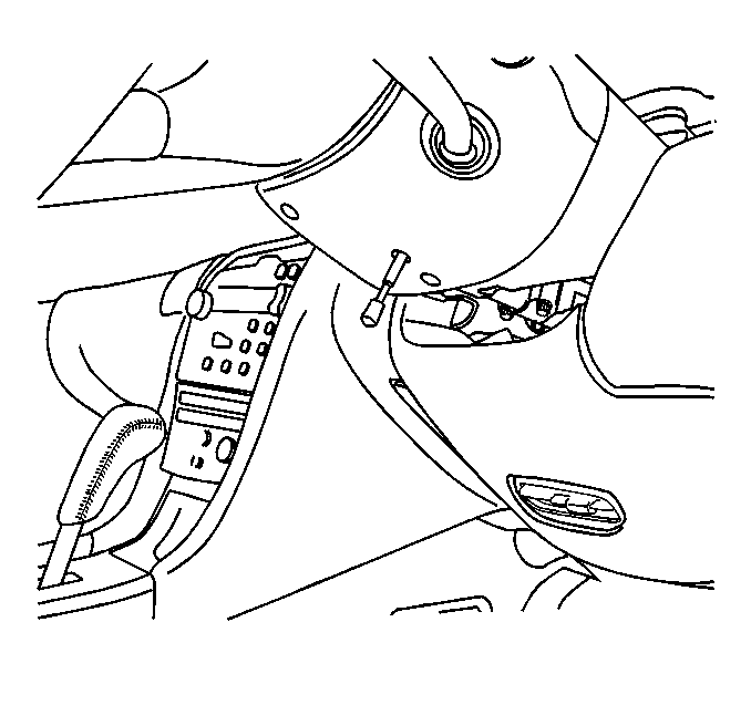
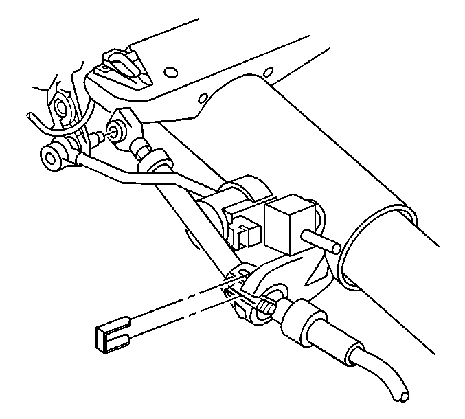
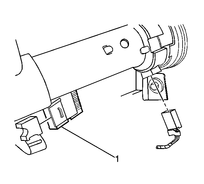
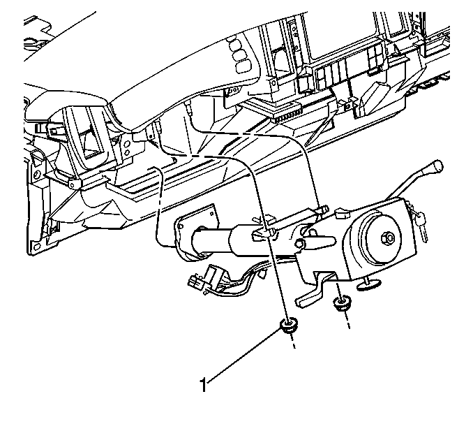
- Disconnect the steering column wiring harness connector (1) from the main body wiring harness.
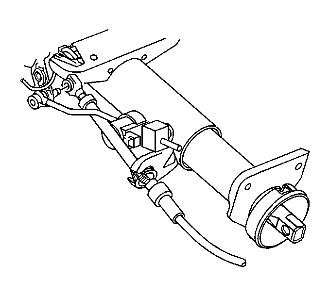
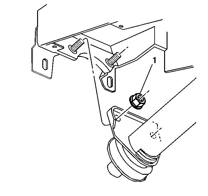
- Remove the support retaining nuts (1) from the lower steering column.
- Support the steering column.
- Position a 13-mm crowfoot wrench onto one of the nuts which secures the steering column to the I/P.
- While holding the stud in position with a #7 inverted TORX® socket, remove the nut.
- Repeat the above steps for each nut.
- Remove the steering column from the vehicle.
- Transfer any necessary components.
Notice: The wheels of the vehicle must be straight ahead and the steering column in the LOCK position before disconnecting the steering column or intermediate shaft from the steering gear. Failure to do so will cause the SIR coil assembly to become uncentered, which may cause damage to the coil assembly.
Notice: Once the steering column is removed from the car, the column is extremely susceptible to damage. Dropping the column on its end could collapse the steering shaft or loosen the plastic injections which maintain column rigidity. Leaning on the column could cause the jacket to bend or deform. Any of the above damage could impair the column's collapsible design. If it is necessary to remove the steering wheel, use only the specified steering wheel puller. Under no conditions should the end of the shaft be hammered upon as hammering could loosen plastic injections which maintain column rigidity.
Notice: The steering column should never be supported only by the lower support bracket. Damage to the lower support could result.
Caution: This vehicle is equipped with a Supplemental Inflatable Restraint (SIR) System. Failure to follow the correct procedure could cause the following conditions:
• Air bag deployment • Personal injury • Unnecessary SIR system repairs • Refer to SIR Component Views in order to determine if you are performing service on or near the SIR components or the SIR wiring. • If you are performing service on or near the SIR components or the SIR wiring, disable the SIR system. Refer to Disabling the SIR System.
Notice: The steering column should never be supported only by the lower support bracket. Damage to the lower support could result.
Important: Stabilize the studs in order to remove the nuts securing the steering column to the instrument panel.
Important: Discard the clips at the upper steering column support, if equipped. These clips are for assembly plant usage only.
Installation Procedure
- Install the steering column to the vehicle.
- Install the mounting nuts (1) to the lower support bracket studs.
- Support the column. Install the mounting nuts (1) to the upper support bracket studs.
- Connect the steering column wiring harness connector (1) to the main body wiring harness.
- Install the shift lever cable to the steering column.
- Install the shift cable to the linear shift assembly.
- Install the retaining clip the shift cable.
- Install the I/P trim panel. Refer to Instrument Panel Lower Trim Panel Replacement in Instrument Panel, Gages, and Console.
- Raise the vehicle.
- Install the intermediate shaft to the steering gear stub shaft.
- Install the lower pinch bolt to the intermediate shaft.
- Install the left front tire. Refer to Tire and Wheel Removal and Installation in Tires and Wheels.
- Lower the vehicle.
- Remove J 42640 from the steering column.
- Enable the SIR system. Refer to Enabling the SIR System in SIR.
- Inspect the steering for proper operation.
Caution: In order to ensure the intended function of the steering
column in a vehicle during a crash and in order to avoid personal injury to
the driver, perform the following:
• Tighten the steering column lower fasteners before you tighten
the steering column upper fasteners. Failure to do this can damage the steering
column. • Tighten the steering column fasteners to the specified torque.
Overtightening the upper steering column fasteners could affect the steering
column collapse.
Notice: If a service replacement steering column is being installed, do not remove the anti-rotation pin until after the steering column has been connected to the steering gear. Removing the anti-rotation pin before the steering column is connected to the steering gear may damage the SIR coil assembly.
Important:
• When installing the steering column, install the fasteners needed for
completing each step of the installation. DO NOT tighten the fasteners until
the procedure tells you to do so. • In order to ensure that the column absorbs energy correctly, use only
the specified screws, bolts, and nuts. Tighten the components to the specified
torque.
Notice: Use the correct fastener in the correct location. Replacement fasteners must be the correct part number for that application. Fasteners requiring replacement or fasteners requiring the use of thread locking compound or sealant are identified in the service procedure. Do not use paints, lubricants, or corrosion inhibitors on fasteners or fastener joint surfaces unless specified. These coatings affect fastener torque and joint clamping force and may damage the fastener. Use the correct tightening sequence and specifications when installing fasteners in order to avoid damage to parts and systems.
Tighten
Tighten the nuts to 27 N·m (20 lb ft).
Tighten
Tighten the bolt to 47 N·m (35 lb ft).