For 1990-2009 cars only
Tools Required
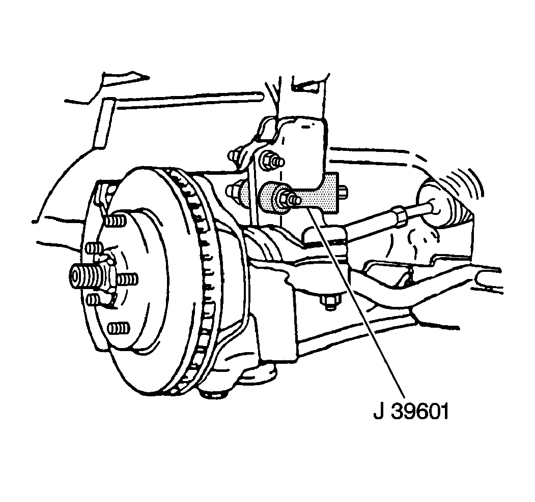
J 39601 Camber Adjustment Tool
- Raise and support the vehicle. Refer to Lifting and Jacking the Vehicle in General Information.
- Remove the tire and wheel. Refer to Tire and Wheel Removal and Installation in Tires and Wheels.
- Tap the upper and lower bolt and nut from the strut and knuckle.
- Separate the strut from the knuckle.
- Using a round file or a die grinder file the inner metal plate to the outside plates diameter.
- File excess metal to make the slotted holes.
- Paint the exposed metal with rust preventive paint or primer.
- Replace the strut to the knuckle.
- Install both the upper and lower bolts.
- Do not tighten at this time.
- Install the J 39601 to the bottom strut bolt.
- Using the J 39601 , set the camber. Refer to Wheel Alignment Specifications .
- Remove the J 39601 .
- Tighten the lower strut to knuckle nut to 225 N·m (166 lb ft).
- Replace the tire and wheel. Refer to Tire and Wheel Removal and Installation in Tires and Wheels.
- Lower the vehicle.
- Perform a wheel alignment. Refer to Wheel Alignment Specifications in Wheel Alignment.

Notice: Do not turn the bolts. Turning the bolts will result in damage to the serrated shoulder of the bolts.
Important: It is necessary to grind the lower bolt hole on the strut to achieve proper camber setting.
If camber specification is not achieved by this procedure check for bent or worn parts.Notice: Refer to Fastener Notice in the Preface section.
Tighten
Tighten the upper strut to knuckle nut to 147 N·m (108 lb ft).
