For 1990-2009 cars only
Removal Procedure
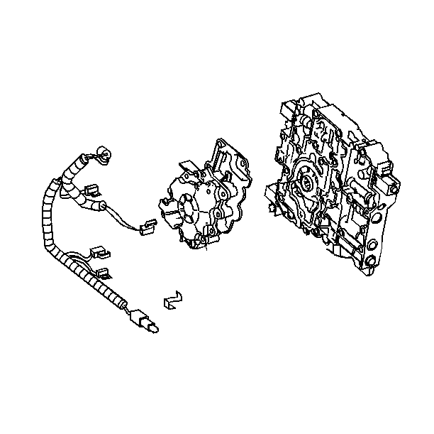
- Remove the case side cover. Refer to Control Valve Body Cover Replacement .
- Remove the wiring harness as necessary.
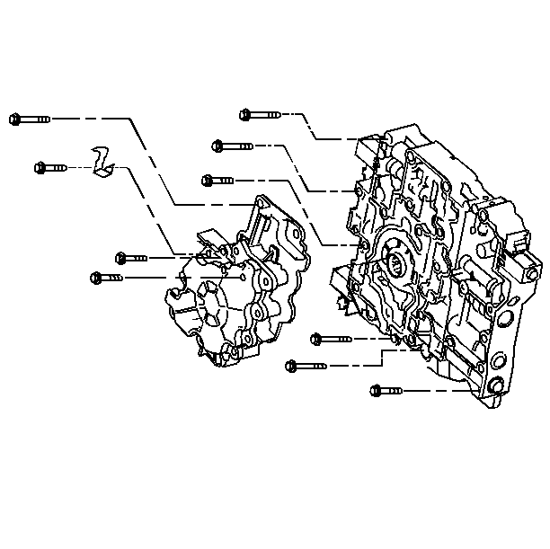
- Remove the oil pump to valve body bolts.


Installation Procedure
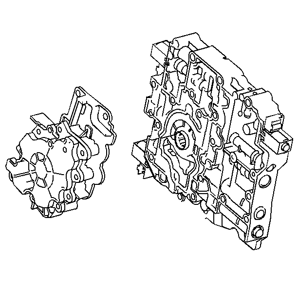
- Install the oil pump to the valve body.
- Install the oil pump to valve body bolts.
- Install the wiring harness, if removed.
- Install the case side cover. Refer to Control Valve Body Cover Replacement .
- Fill the transaxle to the proper level. Refer to Fluid Capacity Specifications .
- Inspect the transaxle fluid level. Refer to Transmission Fluid Check .
- Inspect for fluid leaks.
- Reset the TAP values. Refer to Transmission Adaptive Functions .

Notice: Refer to Fastener Notice in the Preface section.

Notice: Use a torque wrench to tighten the pump to valve body bolts. Do not exceed the torque specifications.
Tighten
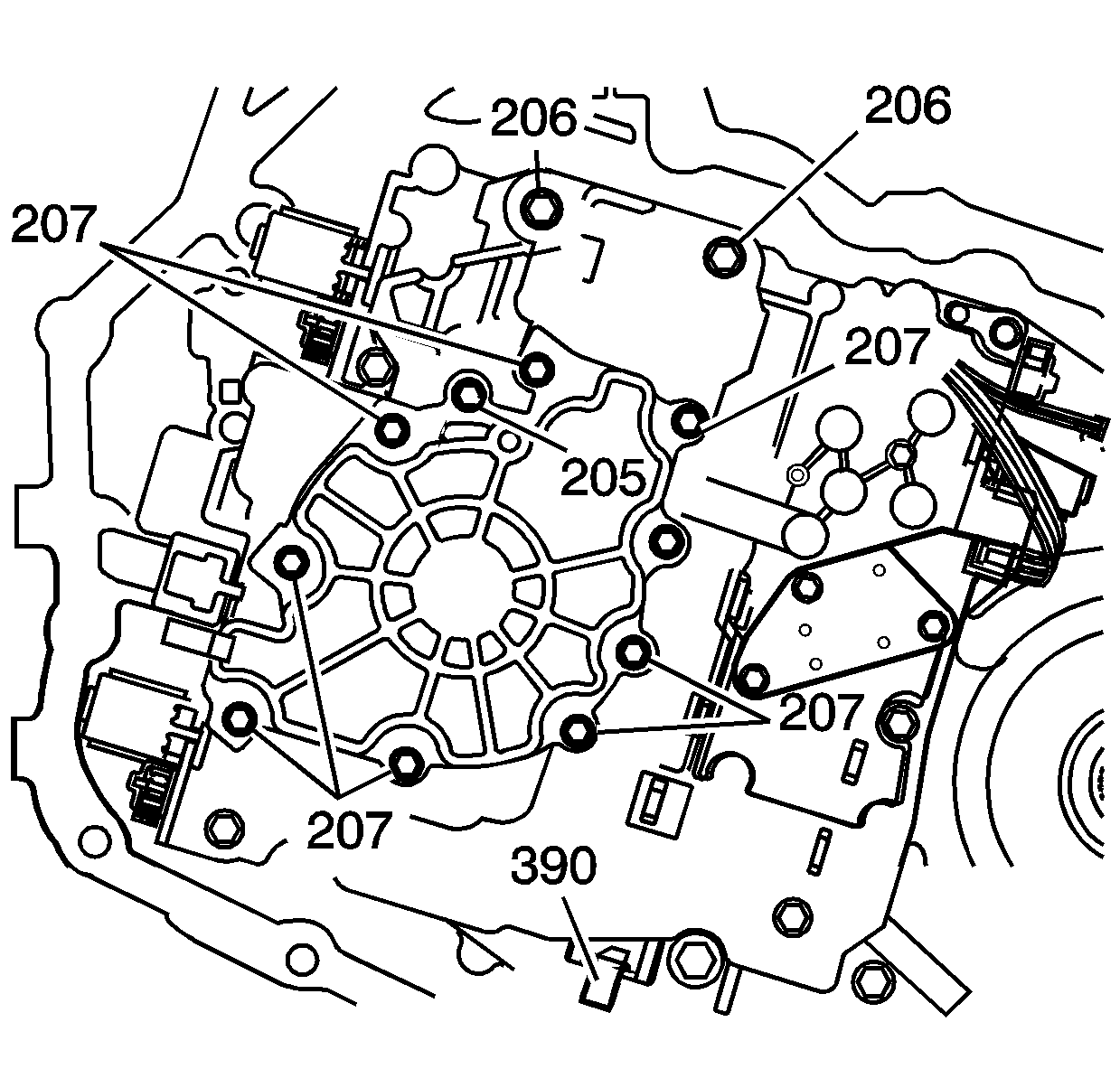
| • | Tighten the valve body bolts (205) to 8 N·m (70 lb in). |
| • | Tighten the valve body bolts (206) to 16 N·m (123 lb in). |
| • | Tighten the valve body bolts (207) to 12 N·m (106 lb in). |

Important: It is recommended that transmission adaptive pressure (TAP) information be reset.
Resetting the TAP values using a scan tool will erase all learned values in all cells. As a result, The ECM, PCM or TCM will need to relearn TAP values. Transmission performance may be affected as new TAP values are learned.