Tools Required
J 38778 Door Trim Pad and Garnish Clip Remover
Removal Procedure
- Remove the front seat assembly. Refer to Seat Replacement .
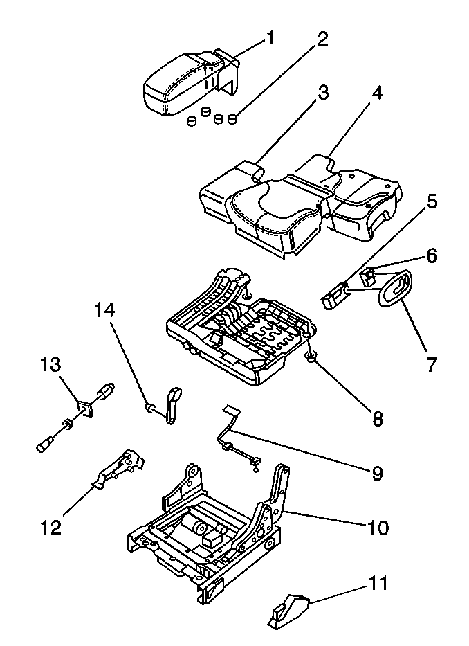
- Remove the seat switch and bezel assembly (5, 6, 7). Refer to Power Seat Switch Replacement .
- On the 60/40 seat, remove the armrest assembly (1). Refer to Front Seat Armrest Replacement .
- Remove the 4 nuts.
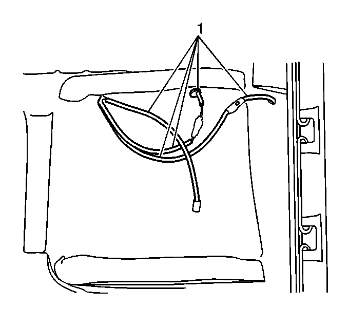
- Disconnect the heated seat wire harness (1), if equipped.
- Disconnect the auxiliary power outlet electrical connector, if equipped.
- Remove the 4 nuts (8) on the bottom in each corner of the seat pan.
- Remove the seat pan and the seat cushion (4) as 1 piece.
- Remove fastener retaining auxiliary power outlet if necessary.
- Remove the power outlet (13).
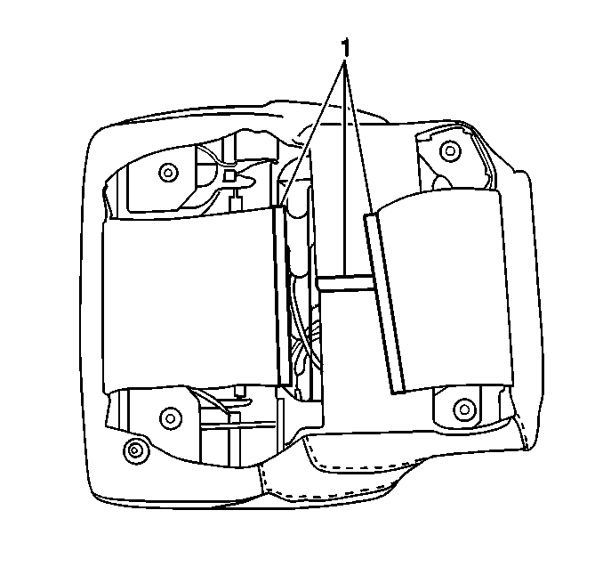
- Remove the J-channel (1) from the following components:
- Use the J 38778 in order to remove the push in retainer securing the seat cover to the seat pan.
- Remove the fasteners retaining the seat cover to the seat switch bezel (7) mounting opening.
- Remove the seat cushion cover (3) and the seat cushion (4).


| • | The front-to-rear flaps |
| • | The side-to-side flaps |

Installation Procedure
- Install the seat cushion (4) on the seat pan.
- Align the seat cushion cover (3) on the seat cushion (4).
- Feed the heated seat wire harness (1) through the cushion, if equipped.
- Work the seat cushion cover (3) over the sides of the cushion (4) and around the seat pan.
- Install the J-channel (1) on the following components:
- Install the retainer fastening the seat cover and cushion (4) to the seat pan.
- Refasten the seat cover (3) to the seat switch bezel (7) opening.
- Install the auxiliary power outlet (13) if necessary.
- Install the seat pan with the cushion and the cover on the seat frame assembly (10).
- Install the 4 nuts (8).
- Feed the wires from the power seat switch (5) through the side of the seat cushion cover (3).
- Install the seat switch (5) and the bezel assembly (7). Refer to Power Seat Switch Replacement .
- Install the armrest assembly (1), if equipped. Refer to Front Seat Armrest Replacement .
- Install the 4 nuts to the armrest.
- Connect the electrical connector.
- Install the front seat assembly. Refer to Seat Replacement .


| • | The front-to-rear flaps |
| • | The side-to-side flaps |

Notice: Use the correct fastener in the correct location. Replacement fasteners must be the correct part number for that application. Fasteners requiring replacement or fasteners requiring the use of thread locking compound or sealant are identified in the service procedure. Do not use paints, lubricants, or corrosion inhibitors on fasteners or fastener joint surfaces unless specified. These coatings affect fastener torque and joint clamping force and may damage the fastener. Use the correct tightening sequence and specifications when installing fasteners in order to avoid damage to parts and systems.
Tighten
Tighten the seat pan nuts to 24 N·m (18 lb ft).
Tighten
Tighten the armrest nuts to 24 N·m (18 lb ft).
