For 1990-2009 cars only
Tools Required
| • | J 36660-A Torque Angle Meter |
| • | J 42385-200 Thread Repair Kit |
Removal Procedure
- Remove the generator bracket. Refer to Generator Bracket Replacement .
- Remove the coolant air bleed pipe. Refer to Coolant Air Bleed Pipe Assembly Replacement.
- Remove the left exhaust manifold. Refer to Exhaust Manifold Replacement - Left Side .
- Remove the pushrods. Refer to Valve Rocker Arm and Push Rod Replacement .
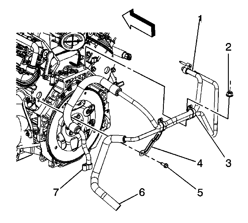
- If equipped, remove the auxiliary air conditioning (A/C) bracket bolt (5).
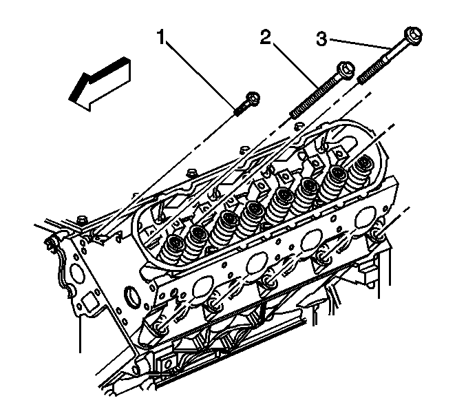
- Remove and discard the cylinder head bolts (1, 2, 3).
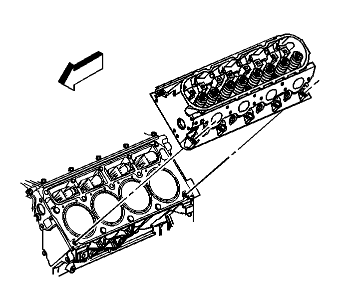
- Remove the cylinder head.
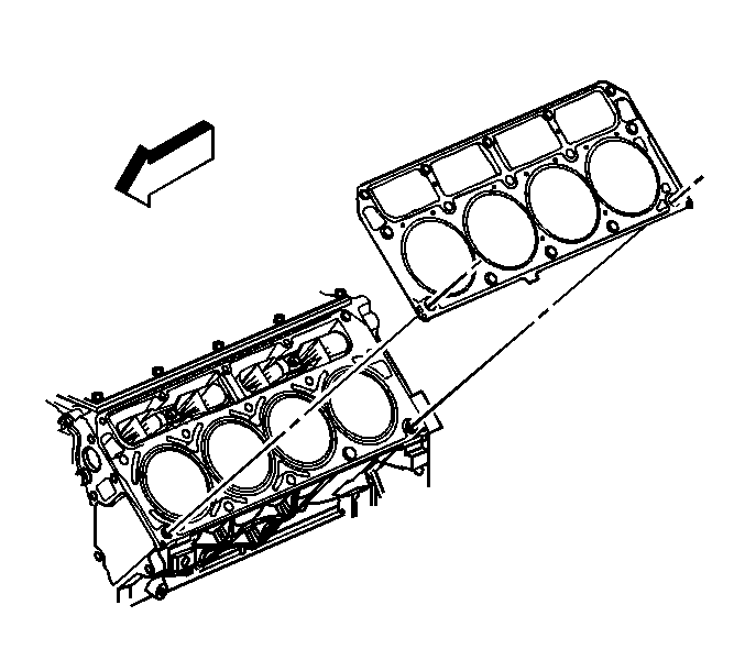
- Remove and discard the cylinder head gasket.
- Clean and inspect the cylinder head. Refer to Cylinder Head Cleaning and Inspection .


Important: The cylinder head bolts are NOT reusable.

Notice: After removal, place the cylinder head on 2 wood blocks in order to prevent damage to the sealing surfaces.

Installation Procedure
- If equipped, install the auxiliary A/C bracket bolt (5).
- Install the pushrods. Refer to Valve Rocker Arm and Push Rod Replacement .
- Install the left exhaust manifold. Refer to Exhaust Manifold Replacement - Left Side .
- Install the coolant air bleed pipe. Refer to Coolant Air Bleed Pipe Assembly Replacement.
- Install the generator bracket. Refer to Generator Bracket Replacement .
Notice: Refer to Fastener Notice in the Preface section.

Tighten
Tighten the bolt to 20 N·m (15 lb ft).
