Transfer Case Holding Fixture Installation
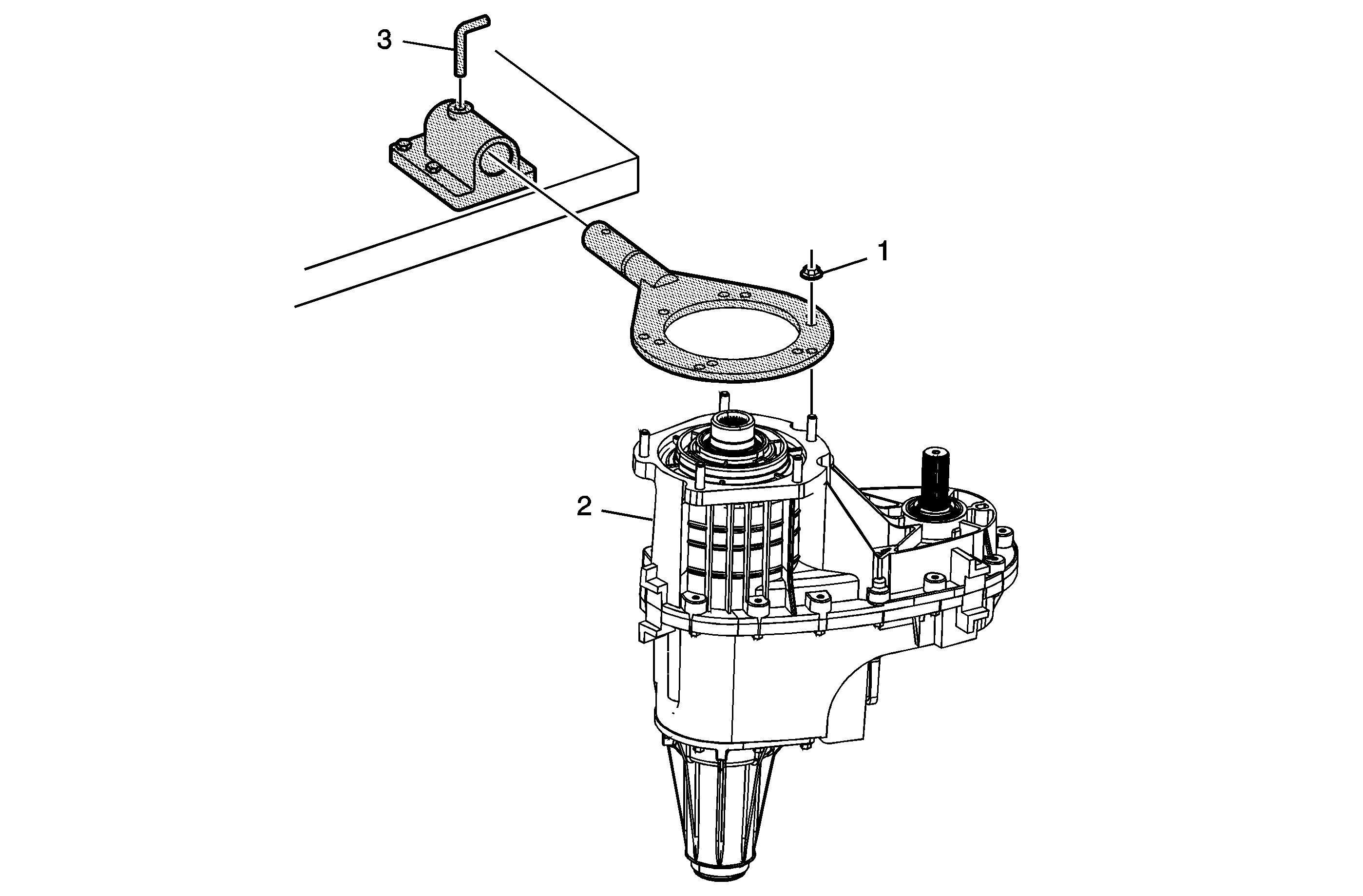
Callout | Component Name | ||||
|---|---|---|---|---|---|
1 | Attachment Nuts Special ToolsJ 45759 Assembly Fixture | ||||
2 | Transfer Case Special ToolsJ 3289-20 Holding Fixture | ||||
3 | Pivot Pin Tip
|
Vehicle Speed Sensor, Vent Pipe, Fill and Drain Plug Removal
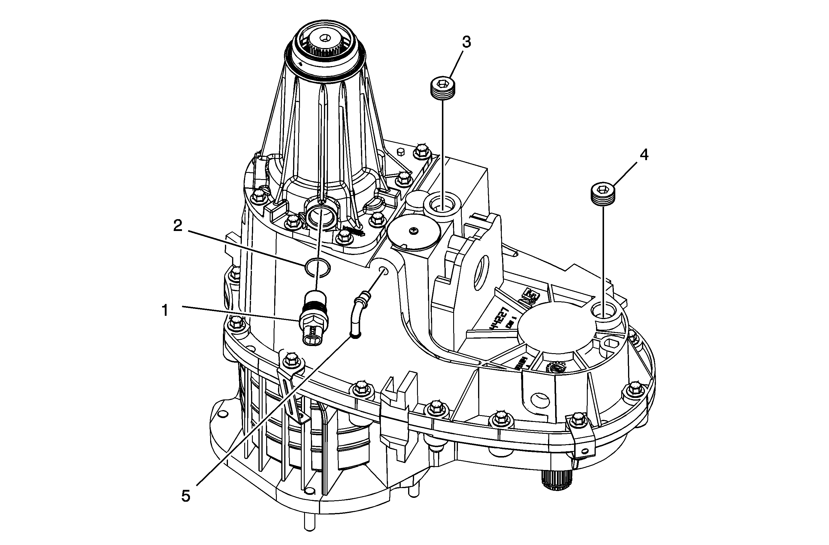
Callout | Component Name |
|---|---|
1 | Vehicle Speed Sensor |
2 | Vehicle Speed Sensor O-Ring |
3 | Transfer Case Oil Fill Plug |
4 | Transfer Case Oil Drain Plug |
5 | Transfer Case Vent Pipe Tip |
Rear Output Shaft Seal and Bushing Removal
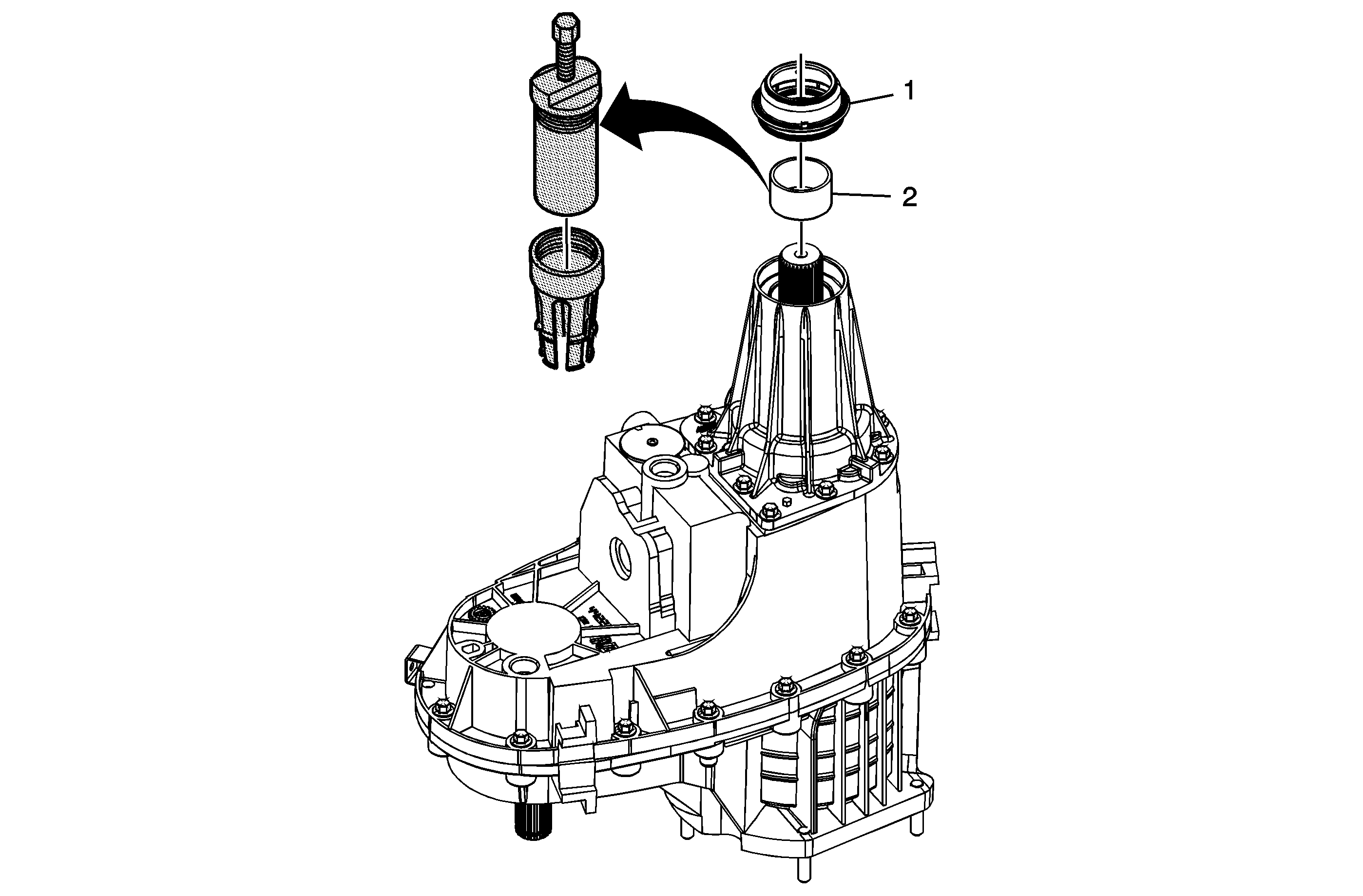
Callout | Component Name |
|---|---|
1 | Transfer Case Rear Output Shaft Seal Notice: Refer to Transfer Case Seal Removal Notice in the Preface section. |
2 | Transfer Case Extension Bushing Tip Special ToolsJ 45380 Transfer Case Rear Bushing Remover and Installer Tip
|
Rear Output Shaft Rear Bearing Retainer Assembly and Oil Pump Removal
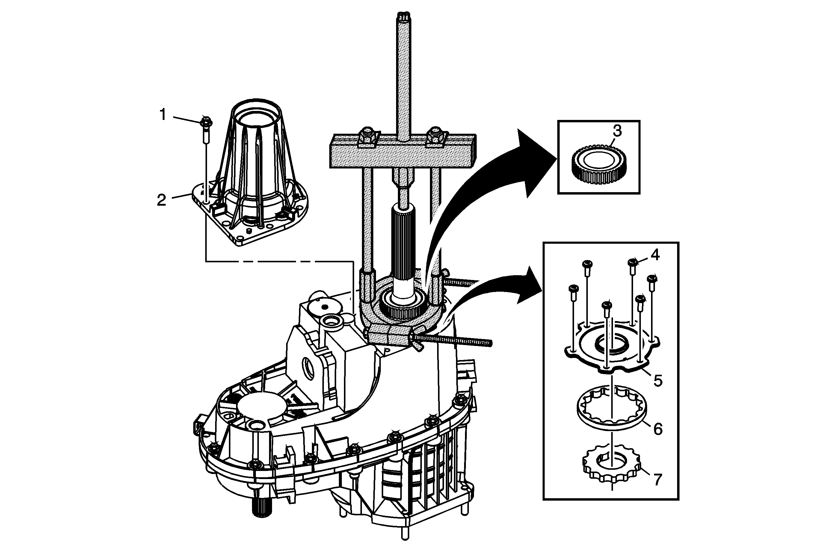
Callout | Component Name | ||||||
|---|---|---|---|---|---|---|---|
1 | Transfer Case Bolts (Qty: 23) | ||||||
2 | Transfer Case Rear Output Shaft Rear Bearing Retainer Assembly | ||||||
3 | Transfer Case Rear Output Shaft Speed Reluctor Wheel Tip Special Tools
| ||||||
4 | Transfer Case Oil Pump Cover Bolts (Qty: 6) | ||||||
5 | Transfer Case Oil Pump Cover | ||||||
6 | Transfer Case Oil Pump Driven Gear | ||||||
7 | Transfer Case Oil Pump Drive Gear |
Transfer Case Rear Case Half Removal
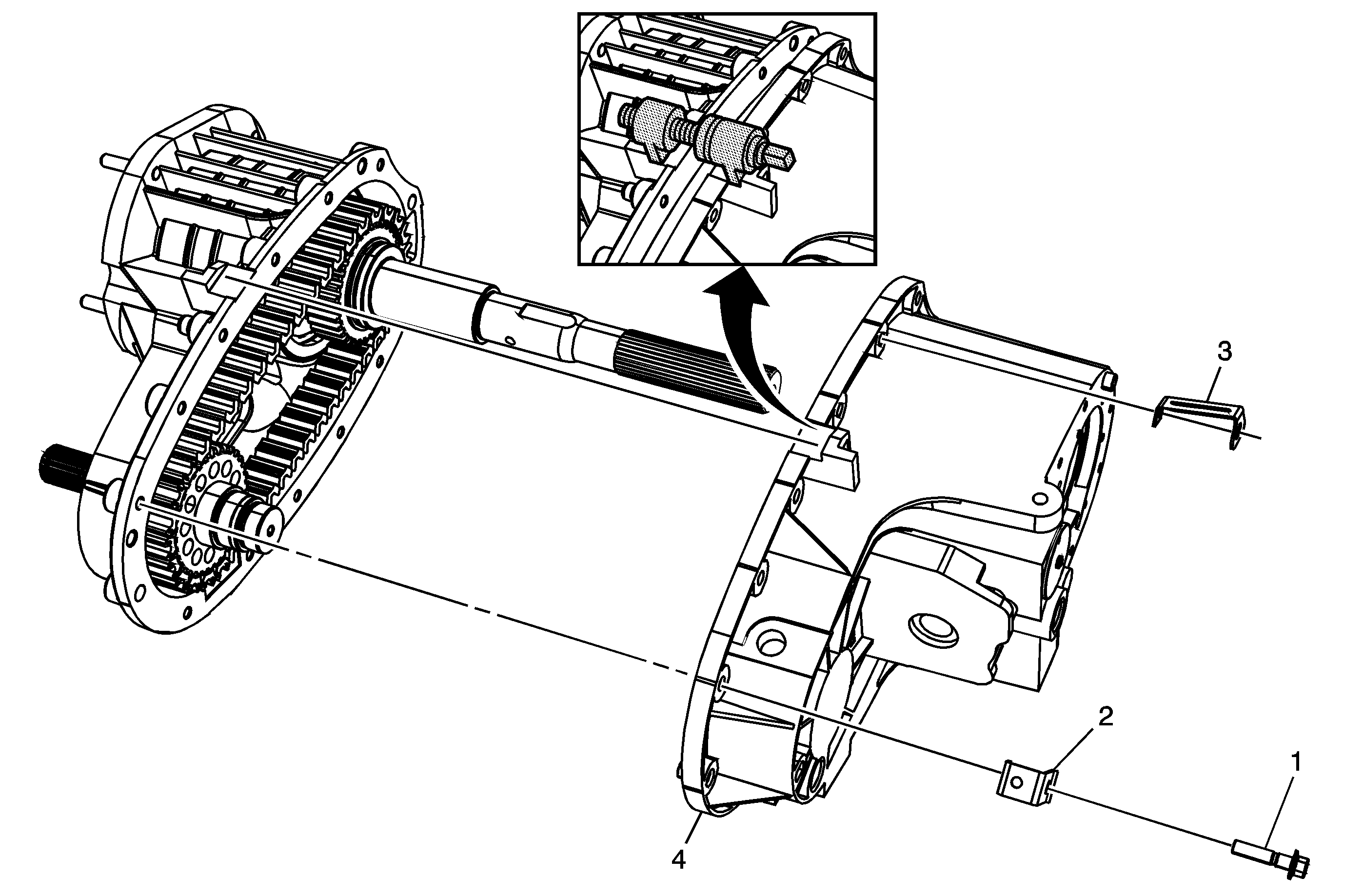
Callout | Component Name |
|---|---|
1 | Transfer Case Bolts (Qty: 23) |
2 | Transfer Case Front Shaft Side Bracket |
3 | Transfer Case Mainshaft Side Bracket |
4 | Transfer Case Rear Case Half Notice: Refer to Machined Surface Damage Notice in the Preface section. Special ToolsJ 45358 Case Spreader |
Oil Pump Suction Pipe Removal
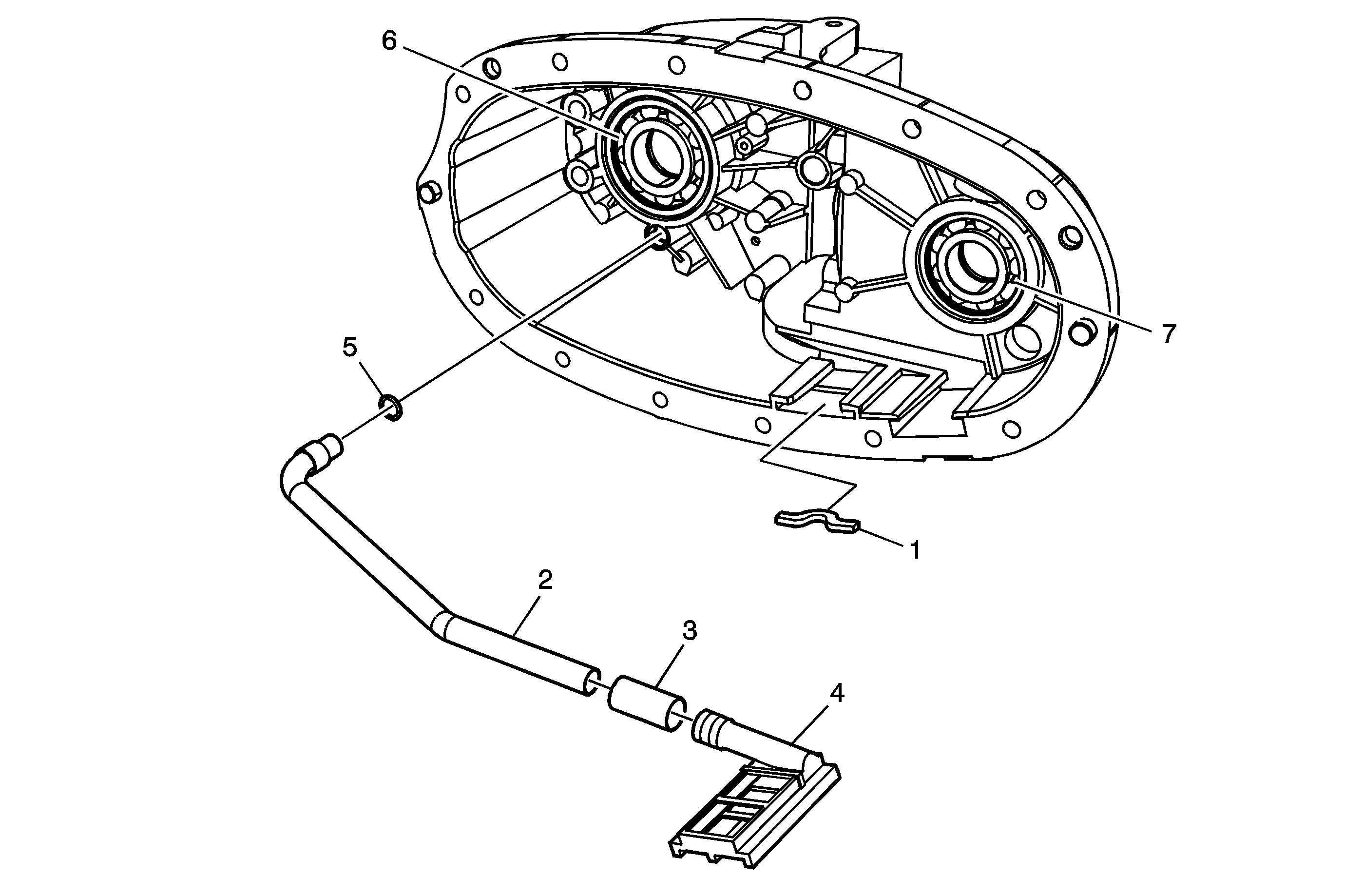
Callout | Component Name |
|---|---|
1 | Transfer Case Chip Collector Magnet |
2 | Transfer Case Oil Pump Suction Pipe |
3 | Transfer Case Oil Pump Hose |
4 | Transfer Case Oil Pump Screen |
5 | Transfer Case Oil Pump Suction Pipe O-Ring Seal |
6 | Transfer Case Rear Output Shaft Bearing Assembly Tip |
7 | Transfer Case Front Output Shaft Rear Bearing Tip |
Drive Chain and Sprockets Removal
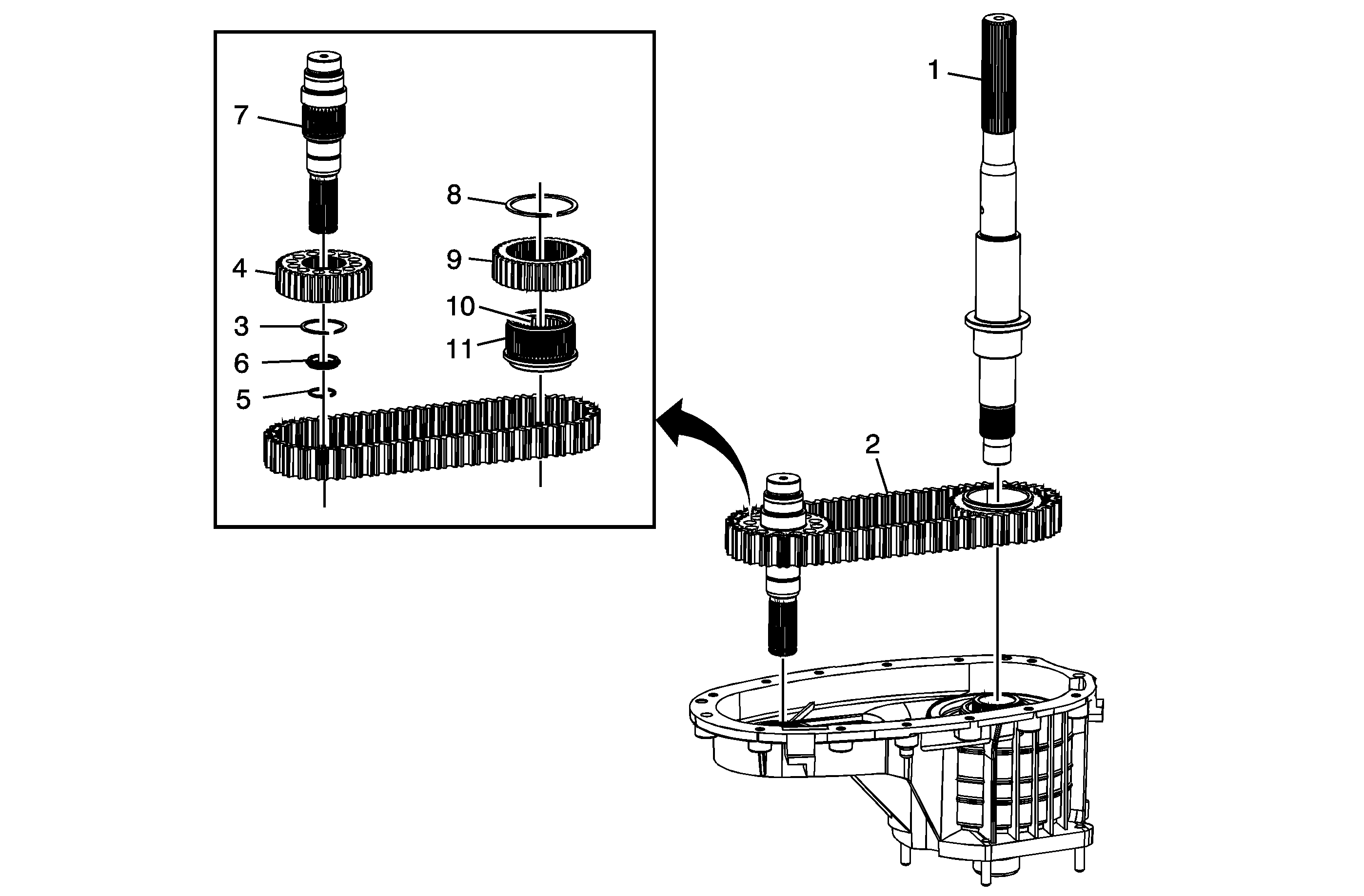
Callout | Component Name | ||||
|---|---|---|---|---|---|
1 | Transfer Case Rear Output Shaft | ||||
2 | Transfer Case Two/Four Wheel Drive Chain Tip
| ||||
3 | Transfer Case Two/Four Wheel Drive Driven Sprocket Outer Retaining Ring | ||||
4 | Transfer Case Two/Four Wheel Drive Driven Sprocket | ||||
5 | Transfer Case Front Output Shaft Bearing Retaining Yoke Ring | ||||
6 | Transfer Case Shaft to Yoke Seal | ||||
7 | Transfer Case Front Output Shaft | ||||
8 | Transfer Case Two/Four Wheel Drive Drive Sprocket Outer Retaining Ring | ||||
9 | Transfer Case Front Output Shaft Drive Sprocket | ||||
10 | Transfer Case Front Output Shaft Drive Sprocket Bearing Tip | ||||
11 | Transfer Case Four Wheel Drive Clutch Hub Assembly |
Front/Rear Drive Differential Carrier Assembly and Front Case Seals Removal
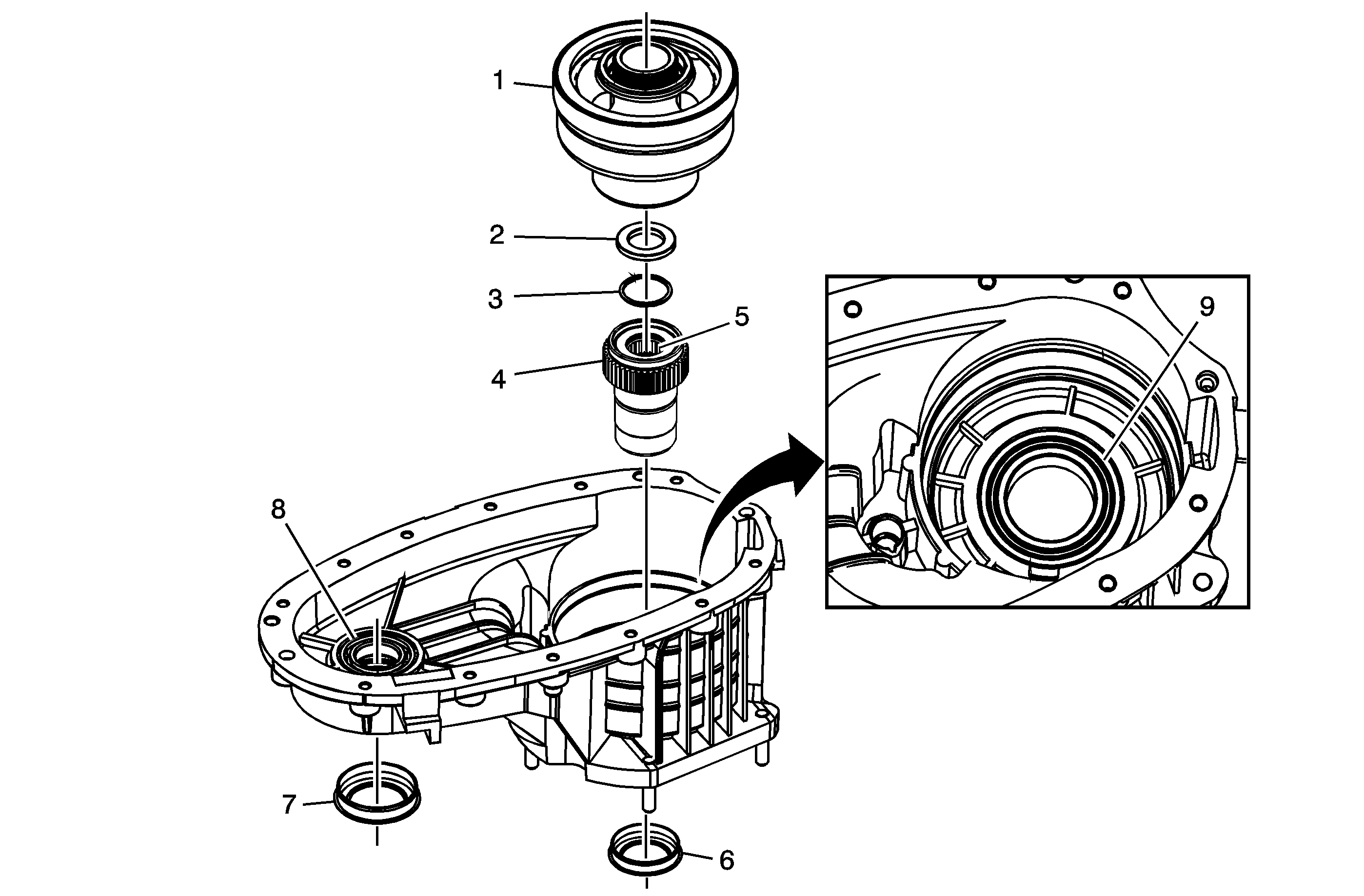
Callout | Component Name |
|---|---|
1 | Front/Rear Drive Differential Carrier Assembly |
2 | Transfer Case Input Shaft Thrust Bearing Washer |
3 | Transfer Case Wave Washer |
4 | Transfer Case Input Shaft Tip |
5 | Transfer Case Input Gear Thrust Bearing Tip |
6 | Transfer Case Input Shaft Seal |
7 | Transfer Case Front Output Shaft Seal |
8 | Transfer Case Front Output Shaft Front Bearing Tip |
9 | Transfer Case Front Input Double Row Ball Bearing Tip |
