CARBURETED FLOAT ADJ. TOOL ESSENTIAL NEW TOOL PACKAGE

VEHICLES AFFECTED: Vehicles Equipped With Quadrajet, Dualjet, Varajet and Monojet Carburetors
A new float positioning tool package, J-34817, has been released for making float adjustments on Quadrajet, Dualjet, Varajet and Monojet carburetors. The float positioning tool, J-34817-3, permits more accurate positioning of the float at the correct checking location than was possible previously, using two fingers. Separate bending tools for each of these carburetor models are supplied in the package to assist in this float level adjustment.
The tool package is available as part number BT-8426 from Borroughs Tool and Equipment Corp. or as J-34817 from Kent-Moore.
The revised float adjustment procedures follow:
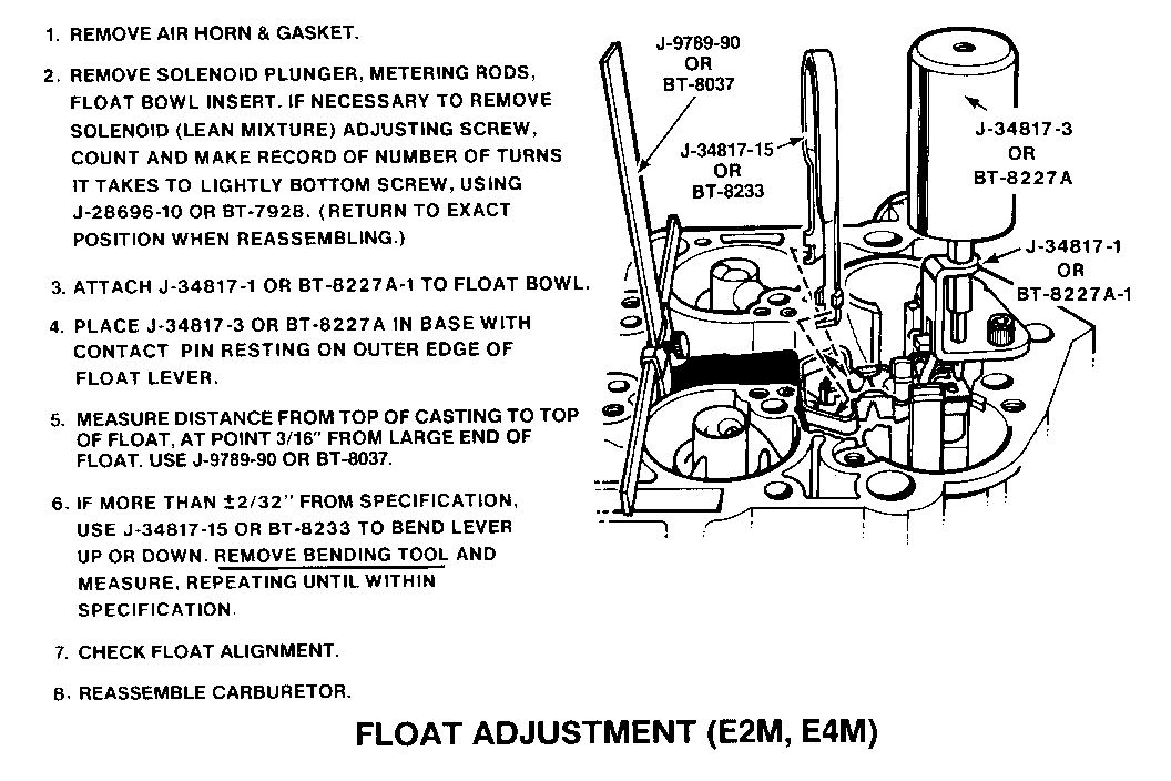
1. REMOVE AIR HORN & GASKET
2. REMOVE SOLENOID PLUNGER, METERING RODS, FLOAT BOWL INSERT. IF NECESSARY TO REMOVE SOLENOID (LEAN MIXTURE) ADJUSTING SCREW, COUNT AND MAKE RECORD OF NUMBER OF TURNS IT TAKES TO LIGHTLY BOTTOM SCREW, USING J-28696-10 OR BT-7928 (RETURN TO EXACT POSITION WHEN REASSEMBLING.)
3. ATTACH J-34817-1 OR BT-8227A-1 TO FLOAT BOWL.
4. PLACE J-34817-3 OR BT-8227A IN BASE WITH CONTACT PIN RESTING ON OUTER EDGE OF FLOAT LEVER.
5. MEASURE DISTANCE FROM TOP OF CASTING TO TOP OF FLOAT, AT POINT 3/16" FROM LARGE END OF FLOAT. USE J-9789-90 OR BT-8037.
6. IF MORE THAN +/- 2/32" FROM SPECIFICATION, USE J-34817-15 OR BT 8233 TO BEND LEVER UP OR DOWN. REMOVE BENDING TOOL AND MEASURE, REPEATING UNIIL WITHIN SPECIFICATION.
7. CHECK FLOAT ALIGNMENT.
8. REASSEMBLE CARBURETOR
FLOAT ADJUSTMENT (E2M, E4M)
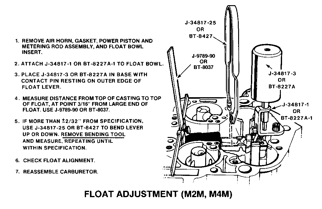
1. REMOVE AIR HORN, GASKET, POWER PISTON AND METERING ROD ASSEMBLY, AND FLOAT BOWL INSERT.
2. ATTACH J-34817-1 OR BT-8227A-1 TO FLOAT BOWL.
3. PLACE J-34817-3 OR BT-8227 A IN BASE WITH CONTACT PIN RESTING ON OUTER EDGE OF FLOAT LEVER.
4. MEASURE DISTANCE FROM TOP OF CASTING TO TOP OF FLOAT, AT POINT 3/16" FROM LARGE END OF FLOAT. USE J-9789-90 OR BT-8037.
5. IF MORE THAN +/- 2/32" FROM SPECIFICATON, USE J-34817-25 OR BT8427 TO BEND LEVER UP OR DOWN. REMOVE BENDING TOOL AND MEASURE, REPEATING UNTIL WTHIN SPECIFICATON.
6. CHECK FLOAT ALIGNMENT
7. REASSEMBLE CARBURETOR.
FLOAT ADJUSTMENT (M2M, M4M)
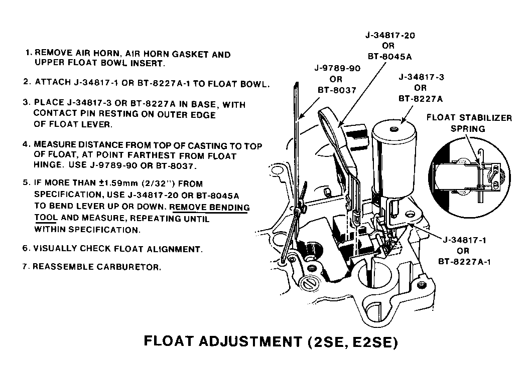
1. REMOVE AIR HORN, AIR HORN GASKET AND UPPER FLOAT BOWL INSERT.
2. ATTACH J-34817-1 OR BT-8227A-1 TO FLOAT BOWL.
3. PLACE J-34817-3 OR BT-8227A IN BASE, WITH CONTACT PIN RESTING ON OUTER EDGE OF FLOAT LEVER.
4. MEASURE DISTANCE FROM TOP OF CASTING TO TOP OF FLOAT, AT POINT FARTHEST FROM FLOAT HINGE. USE J-97890-90 OR BT-8037.
5. IF MORE THAN +/- 1.59 MM (2/32") FROM SPECIFICAITON, USE J-34817-20 OR BT-8045A TO BEND LEVER UP OR DOWN. REMOVE BENDING TOOL AND MEASURE, REPEATING UNTIL WITHIN SPECIFICATION.
6. VISUALLY CHECK FLOAT ALIGNMENT.
7. REASSEMBLE CARBURETOR.
FLOAT ADJUSTMENT (2SE, E2SE)
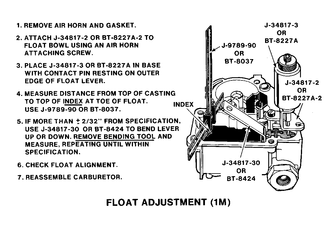
1. REMOVE AIR HORN AND GASKET.
2. ATTACH J-34817-2 OR BT-8227A-2 TO FLOAT BOWL USING AN AIR HORN ATTACHING SCREW.
3. PLACE J-34817-3 OR BT-8227A IN BASE WITH CONTACT PIN RESTING ON OUTER EDGE OF FLOAT LEVER.
4. MEASURE DISTANCE FROM TOP OF CASTING TO TOP OF INDEX AT TOE OF FLOAT. IN USE J-9789-90 OR BT-8037.
5. IF MORE THAN +/- 2/32" FROM SPECIFICATION, USE J-34817-30 OR BT-8424 TO BEND LEVER UP OR DOWN. REMOVE BENDING TOOL AND MEASURE, REPEATING UNTIL WITHIN SPECIFICATION.
6. CHECK FLOAT ALIGNMENT.
7. REASSEMBLE CARBURETOR.
FLOAT ADJUSTMENT (1M)


General Motors bulletins are intended for use by professional technicians, not a "do-it-yourselfer". They are written to inform those technicians of conditions that may occur on some vehicles, or to provide information that could assist in the proper service of a vehicle. Properly trained technicians have the equipment, tools, safety instructions and know-how to do a job properly and safely. If a condition is described, do not assume that the bulletin applies to your vehicle, or that your vehicle will have that condition. See a General Motors dealer servicing your brand of General Motors vehicle for information on whether your vehicle may benefit from the information.
