SERVICE GUILD: TRANSAXLE COMPONENT SERVICABLE

MODELS AFFECTED: ALL 1988 BUICK REGALS
In addition to those listed in the 1988 service manual, the following automatic transaxle components can be serviced on vehicle:
* Case side cover pan and/or gaskets * Pump * Valve Body * Pressure Switch, 3rd and 4th * TCC Solenoid and Wiring Harness
The following procedure steps should be added to the 1988 Service Manual and will be included in all future manuals.
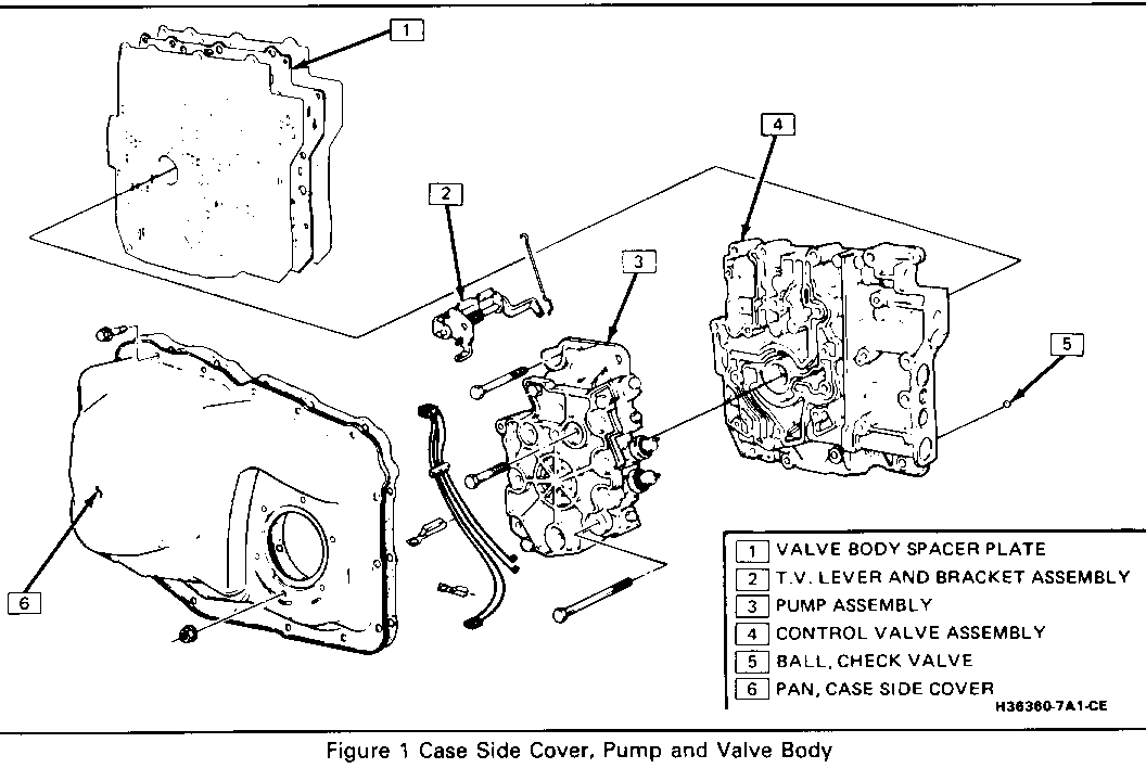
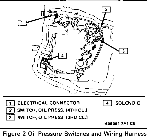
(See Illustrations as well as the chart below)
*************************************************************************** ** Labor ** ** Operation Labor ** ** Number Time ** ** ------ ---- ** ** Case Side Cover Pan and/or Gaskets K6540 3.4 Hr. ** ** ** ** Pump and Valve K6570 4.3 Hr. ** ** ** ** Pressure Switch, 3rd and 4th K6515 3.5 Hr. ** ** ** ** TCC Solenoid and Wiring Harness K6520 3.5 Hr. ** ***************************************************************************
CASE SIDE COVER PAN AND/OR GASKETS ---------------------------------- Figure 1 Tools Required: J 28467-A Engine Support Fixture J 36462 Engine Support Adapter Leg
Remove or Disconnect
1. Negative battery cable 2. Install engine support fixture J 28467-A along with support leg J'36462. 3. Air cleaner housing and intake tube 4. Torque struts at engine mounts 5 Two crossover pipe-to-left manifold bolts 6. Loosen crossover pipe-to-fight manifold clamp. 7. Two bolts at top of transaxle mount bracket. Pry crossover pipe to allow removal of front bolt.
NOTICE: Do not pry on crossover pipe heat shield. If shield is bent, heat damage to other components may occur.
8. Raise vehicle and suitably support (see Section OA). 9. Left front wheel and tire 10. Left front brake caliper and bracket assembly and hang from vehicle
Important
* Do not allow to hang from brake hose. * Install two lug nuts (flat side to rotor) to retain rotor.
11. Four bolts at hub and bearing assembly 12. Left drive axle (see Section 4D) 13. Left lower ball joint 14. Left inner fender splash shield 15. Pinch bolt at intermediate steering shaft (see Section 3B4)
CAUTION:
Failure to disconnect the intermediate shaft from the rack and pinion steering gear stub shaft can result in damage to the steering gear and/or intermediate shaft. This damage may cause loss of steering control which could result in an accident and possible personal injury.
16. Support right and left sides of frame with jackstands. 17. Right frame to body bolts (see Section 2A) 18. Left frame to body bolts, and adjust jackstand to lower left side of frame. 19. Transaxle mount and mount support 20. Lower the left side of engine/transaxle approximately 4-6 inches, using the engine support fixture. 21. Two clamps holding wiring hamess to transaxle mount bracket 22. Transaxle mount bracket 23. Position drain pan under transaxle. 24. Case side cover pan and gasket
Clean
* Case and side cover gasket surfaces
Install or Connect
1. Case side cover pan and gasket 2. Case side cover bolts and channel plate flange nuts
Tighten
* Torque bolts and nuts to 14 N-m (10 lbs. ft.)
3. Transaxle mount bracket (start upper bolts first) 4. Two wiring hamess clamps 5. Raise left side of engine/transaxle using engine support fixture. 6. Transaxle mount and mount support 7. Raise left side of frame and install four frame-to-body bolts.
Tighten
* Torque transaxle mount/mount support nuts/bolts to 48 N-m (35 lbs. ft.). * Torque transaxle mount-to-bracket nuts to 30 N-m (22 lbs. ft.). * Torque front transaxle mount bracket bolts to 48 N-m (35 lbs. ft.). * Torque frame-to-body bolts to 140 N-m (103 lbs. ft.).
8. Remove jackstands. 9. Pinch bolt at intermediate steering shaft (see Section 3B4) 10. Left inner fender splash shield 11. Left lower ball joint 12. Left drive axle (see Section 4D) 13. Four bolts at hub and bearing assembly 14. Left front brake caliper and bracket 15. Left front wheel and tire 16. Lower vehicle 17. Two bolts at top of transaxle mount bracket
Tighten
* Torque bolts to 82 N-m (61 lbs. ft.).
18. Two crossover pipe-to-left manifold bolts 19. Tighten crossover-to-right manifold clamp. 20. Torque struts at engine mounts 21. Remove engine support fixture. 22. Air cleaner housing and intake tube 23. Negative battery cable 24. Refill transaxle to proper level.
Inspect
* For proper completion of repairs * For proper fluid level, adjust as necessary. * For fluid leaks
Pump
Figure 1 Remove or Disconnect -------------------- 1. Negative battery cable 2. Case side cover pan 3. Electrical connections from pressure switches 4. Pump to valve body bolts (14)
NOTICE: Do not remove the three #40 torx bolts which hold the pump assembly together.
* For pump inspection, see Section 440-T4 Unit Repair.
Install or Connect
1. Pump to valve body 2. Valve body bolts
Tighten
* Torque bolts to 14 N-m (10 lbs. ft.) 3. Electrical connections to pressure switches 4. Case side cover pan 5. Negative battery cable 6. Refill transaxle to proper level.
VALVE BODY
Figure 1 Remove or Disconnect -------------------- 1. Negative battery cable 2. Case side cover pan 3. Pump 4. 1-2 servo pipe clip from valve body 5. Valve body to channel plate bolts 6. Valve body, keeping the spacer plate with the transaxle 7. Spacer plate and gasket * For checkball locations, see Section 440-T4 Unit Repair.
Install or Connect
1. Retain checkballs in their proper locations with petroleum jelly. 2. Spacer plate and gasket 3. Valve body and gasket 4. Valve body to channel plate bolts
Tighten
* Torque bolts to 14 N-m (10 lbs. ft.)
Important
* Do not use impact type tools on the valve body or pump assembly.
5. 1-2 servo pipe clip to valve body 6. Pump 7. Case side cover pan 8. Negative battery cable 9. Refill transaxle to proper level 10. Adjust T.V. cable.
PRESSURE SWITCH, 3RD AND 4TH
Figure 2 Remove or Disconnect -------------------- 1. Negative battery cable 2. Case side cover pan 3. Pressure switches at transaxle valve body
Install or Connect
1. Pressure switches 2. Case side cover pan, new gasket and attaching bolts
Tighten * Torque bolts to 14 N-m (10 lbs. ft.) 3. Negative, battery cable 4. Refill transaxle to proper level
TCC SOLENOID AND WIRING HARNESS
Remove or Disconnect
1. Negative battery cable 2. Case side cover pan 3. Screws retaining solenoid 4. Electrical connector and solenoid
Install or Connect
1. Electrical connector and solenoid 2. Retaining screws
Tighten
* Torque screws to 14 N-m (10 lbs. ft.)
3. Case side cover pan, new gasket and attaching bolts
Tighten
* Torque bolts to 14 N-m (10 lbs. ft.)
4. Negative battery cable 5. Refill transaxle to proper level


General Motors bulletins are intended for use by professional technicians, not a "do-it-yourselfer". They are written to inform those technicians of conditions that may occur on some vehicles, or to provide information that could assist in the proper service of a vehicle. Properly trained technicians have the equipment, tools, safety instructions and know-how to do a job properly and safely. If a condition is described, do not assume that the bulletin applies to your vehicle, or that your vehicle will have that condition. See a General Motors dealer servicing your brand of General Motors vehicle for information on whether your vehicle may benefit from the information.
