A/C AND HEATER PUSH-ON FAN REPLACEMENT PROCEDURE

1988 "W" CAR - REPLACEMENT PROCEDURE FOR THE A/C AND HEATER PUSH-ON FAN
VEHICLES AFFECTED: ALL "W" CAR MODELS -----------------
THE FOLLOWING PROCEDURE IS RECOMMENDED WHEN REPLACING THE 1988 "W" CAR A/C AND HEATER PUSH-ON FAN
REMOVE OR DISCONNECT
1. Negative battery cable 2. Right side hush panel 3. Component center 4. Blower motor and resistor electrical connections 5. Retainer clip holding the IP harness conduit to the firewall (at the back and to the right of the motor) 6. Two blower motor screws nearest firewall 7. Grasp carpet at top side of firewall just left of blower motor and pull forward (this will create a pocket for the blower motor and fan to drop into) 8. Remaining screw holding the blower motor 9. Lower blower motor until the rubber mounting grommets on the blower motor are clear of the locating bosses 10. Lower blower motor past the IP harness (if the IP harness interferes remove tape from conduit end nearest the floor and peel back conduit) lower blower motor and fan past the portion of the IP cable with the conduit removed (flatten individual wires against the firewall at a position to allow the flange to pass) 11. Blower and fan assembly from pocket formed by carpet
To install new assembly reverse the above procedure.
I. REMOVE FAN ---------- + USE HEAT KNIFE OR SOLDERING IRON.
o CUT MATERIAL ON SHAFT AXIALLY IN THREE (3) PLACES: STARTING 25 mm (1/2") FROM BASE OF FAN SHAFT, START CUT INTO FAN DOME AND CONTINUE TO CUT THROUGH THE PLASTIC MATERIAL TO THE END OF SHAFT SO THAT THE FAN SPLITS FROM THE SHAFT.
o GRASP FAN AND PULL STRAIGHT OFF THE SHAFT.
NOTICE: DO NOT HAMMER MOTOR OR PLACE HEAVY "SIDE WAY" IMPACT ON FAN OR MOTOR DAMAGE MAY OCCUR
IA. ALTERNATE METHODS TO REMOVE FAN ------------------------------- + USE SMALL WHEEL PULLER.
o REMOVE TIP OF FAN AT END OF MOTOR SHAFT USING SOLDERING IRON OR END CUTTING PLIERS, VISE-GRIP OR CHANNELOCK TYPE PLIERS.
o DRAW FAN FROM MOTOR SHAFT USING A SMALLER PULLER. HOOK LEGS OF PULLER BETWEEN FAN LOWER RIM AND MOTOR MOUNTING PLATE. THREAD CENTER POST OF PULLER AGAINST THE END OF THE MOTOR SHAFT EXPOSED IN THE ABOVE STEP.
+ USE DRILL PRESS OR SMALL ARBOR PRESS.
o REMOVE TIP OF FAN AT END OF MOTOR SHAFT USING SOLDERING IRON OR END CUTTING PLIERS, VISE-GRIP OR CHANNELOCK TYPE PLIERS.
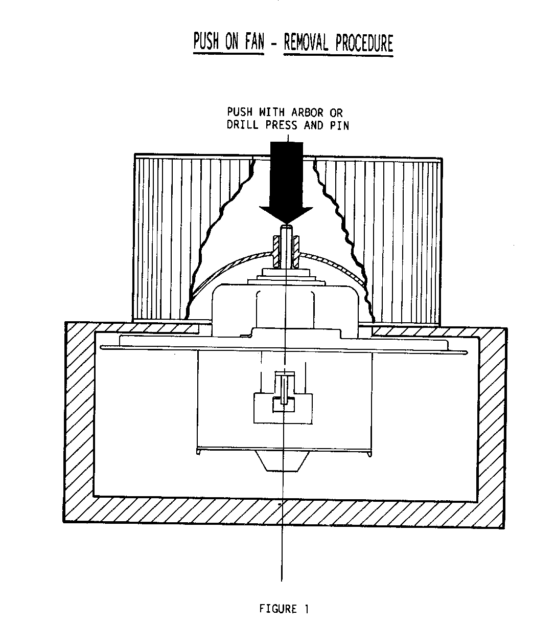
o SUPPORT FAN AS SHOWN IN FIGURE 1, WITH BLOCKS, ANGLE IRON, ETC. WHILE ALLOWING THE MOTOR TO BE SUSPENDED, AS SHOWN.
o PLACE STEADY PRESSURE ON TIP OF MOTOR SHAFT AS SHOWN, WITH A DRILL PRESS OR SMALL ARBOR PRESS AND PIN ARRANGEMENT. MOTOR SHOULD FALL FREELY FROM THE FAN AFTER MOVING MOTOR SHAFT ABOUT 25 mm (1/2 INCH).
NOTICE: DO NOT HAMMER MOTOR OR PLACE HEAVY "SIDE WAY" IMPACT ON FAN OR MOTOR DAMAGE MAY OCCUR
II. FAN INSTALLATION ---------------- + INSERT FAN ON MOTOR SHAFT.
o GRASP FAN BY DOME AND BY APPLYING HAND PRESSURE TO FAN DOME INSERT FAN ON MOTOR SHAFT UNTIL FAN IS LIGHTLY SEATED ON MOTOR SHAFT.
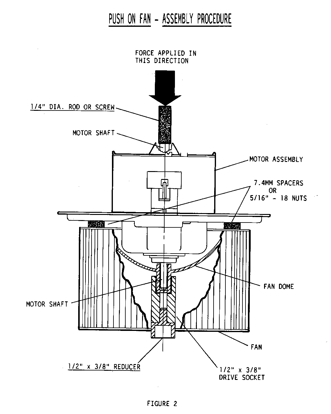
+ PLACE FAN AND MOTOR ON A COMBINATION OF 1/2" X 3/8" DRIVE SOCKET AND 1/2" X 3/8" REDUCER AS SHOWN IN FIGURE 2.
+ WHILE STEADYING THE FAN AND MOTOR, APPLY STEADY FORCE TO THE REAR OF THE MOTOR SHAFT,USING A DRILL PRESS OR SMALL ARBOR PRESS AND PIN ARRANGEMENT, UNTIL THE CLEARANCE BETWEEN THE MOTOR MOUNTING PLATE AND THE FAN HUB is 7.4 mm +/-0.5 MM.
NOTE: A 5/16" X 18 NUT IS APPROXIMATELY 7.2 MM
+ REMOVE THE SPACERS (NUTS) BY GRASPING FAN DOME AND TURNING FAN WHICH WILL DISLODGE SPACERS FROM UNDER FAN.
NOTICE: DO NOT HAMMER ON MOTOR TO INSTALL FAN OR DAMAGE TO MOTOR MAY OCCUR
ADDITIONAL NOTICES:
+ TO PREVENT MOTOR SHAFT/BEARING DAMAGE, DO NOT APPLY FORCE TO MOTOR HOUSING TO SEAT FAN ON MOTOR.
+ TO PREVENT FAN DAMAGE DURING INSTALLATION, DO NOT APPLY PRESSURE TO FAN RIM.
+ IT IS NECESSARY TO ENSURE THE PROPER REPLACEMENT FAN IS USED.
Use the most applicable labour operation from the Canadian Labour Time Guide.


General Motors bulletins are intended for use by professional technicians, not a "do-it-yourselfer". They are written to inform those technicians of conditions that may occur on some vehicles, or to provide information that could assist in the proper service of a vehicle. Properly trained technicians have the equipment, tools, safety instructions and know-how to do a job properly and safely. If a condition is described, do not assume that the bulletin applies to your vehicle, or that your vehicle will have that condition. See a General Motors dealer servicing your brand of General Motors vehicle for information on whether your vehicle may benefit from the information.
