SERVICE MANUAL UPDATE REVISED WHEEL BOLT R AND R PROCEDURE

VEHICLES AFFECTED: 1988 W CARLINES
SERVICE MANUAL UPDATE
The front wheel bolt Repair and Replace procedures are revised with this new art work for Section 3C of.the 1988 Buick W-car final manual and the 1988 Oldsmobile and Pontiac W-car preliminary manuals.
The rear wheel bolt Repair and Replace procedures should be added to Section 3D of the same manuals. The 1988 Oldsmobile and Pontiac W-car final manuals and all subsequent manuals will include these revisions.
WHEEL BOLT (FRONT)
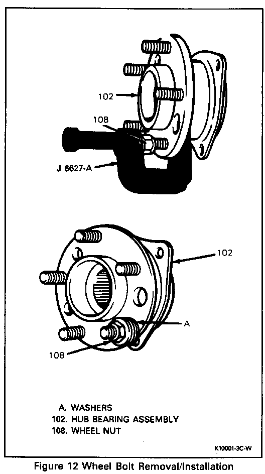
Figure 12 Tool Required: J 6627-A Wheel Bolt Remover
Remove or Disconnect
Important
A 36mm wheel bolt will be used for front service replacement only. Rear service replacement will use the current 43mm production bolt.
1. Raise vehicle (see Section OA).
2. Wheel and tire assembly
3. Brake caliper and bracket assembly, and hang from vehicle. Do not allow to hang by brake hose.
4. Brake rotor
5. Bolt must be 10-12mm shorter than original (43mm) bolt for removal. Cut bolt if necessary and position in the six o'clock position.
6. Using J 6627-A or equivalent, extract bolt from hub.
Clean
Wheel hub flange and rotor of any corrosion, metal chips orforeign material
Install or Connect
1. Shorter replacement bolt in wheel hub
2. Add enough washers (A) to draw bolt into hub.
3. Wheel nut (flat side to washers)
Tighten
Wheel nut until wheel bolt head seats against hub flange.
Important
Make sure wheel bolt is fully seated against hub flange.
4. Back off wheel nut and remove washers
5. Brake rotor
6. Brake caliper and bracket assembly (see Section 5F)
7. Wheel and tire assembly
8. Lower vehicle.
Tighten
Wheel nuts to 140 N-m (100 lbs. ft.)
WHEEL BOLT (REAR)
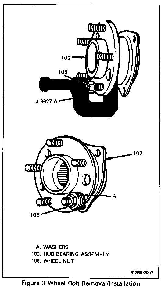
Figure 3
Tools Required:
J 6627-A Wheel Bolt Remover J 36581 Rear Caliper Bolt Torque Wrench Adapter
Remove or Disconnect
1. Raise vehicle (see Section OA).
2. Wheel and tire assembly
3. Brake hose bracket
4. Brake caliper, and hang from vehicle. Do not allow to hang by brake hose. (J 36581 allows easier access for removal as well as installation of caliper bolts.)
5. Brake rotor
6. Using J 6627-A or equivalent, extract bolt from hub.
Clean
Wheel hub flange and rotor of any corrosion, metal chips or foreign material
Install or Connect
1. Replacement bolt in wheel hub
2. Add enough washers (A) to draw bolt into hub.
3. Wheel nut (flat side to washers)
Tighten
Wheel nut until wheel bolt head seats against hub flange.
Important
Make sure that wheel bolt is fully seated against hub flange.
4. Back off wheel nut and remove washers. 5. Brake rotor 6. Brake caliper (see Section 5F) 7. Brake hose bracket (see Section 5F) 8. Wheel and tire assembly 9. Lower vehicle.
Tighten
Wheel nuts to 140 N-m (100 lbs. ft.)


General Motors bulletins are intended for use by professional technicians, not a "do-it-yourselfer". They are written to inform those technicians of conditions that may occur on some vehicles, or to provide information that could assist in the proper service of a vehicle. Properly trained technicians have the equipment, tools, safety instructions and know-how to do a job properly and safely. If a condition is described, do not assume that the bulletin applies to your vehicle, or that your vehicle will have that condition. See a General Motors dealer servicing your brand of General Motors vehicle for information on whether your vehicle may benefit from the information.
