SERVICE MANUAL UPDATE ELECTRICAL DIAGNOSIS

VEHICLES AFFECTED: 1988 W CAR
The following pages reflect connections and/or product changes. These pages are contained herein:
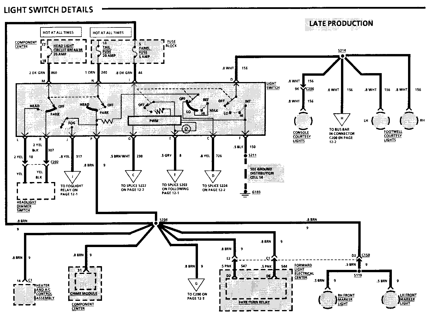
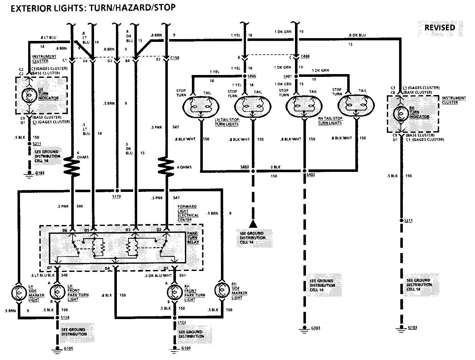
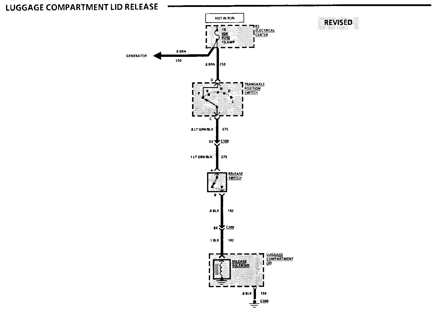
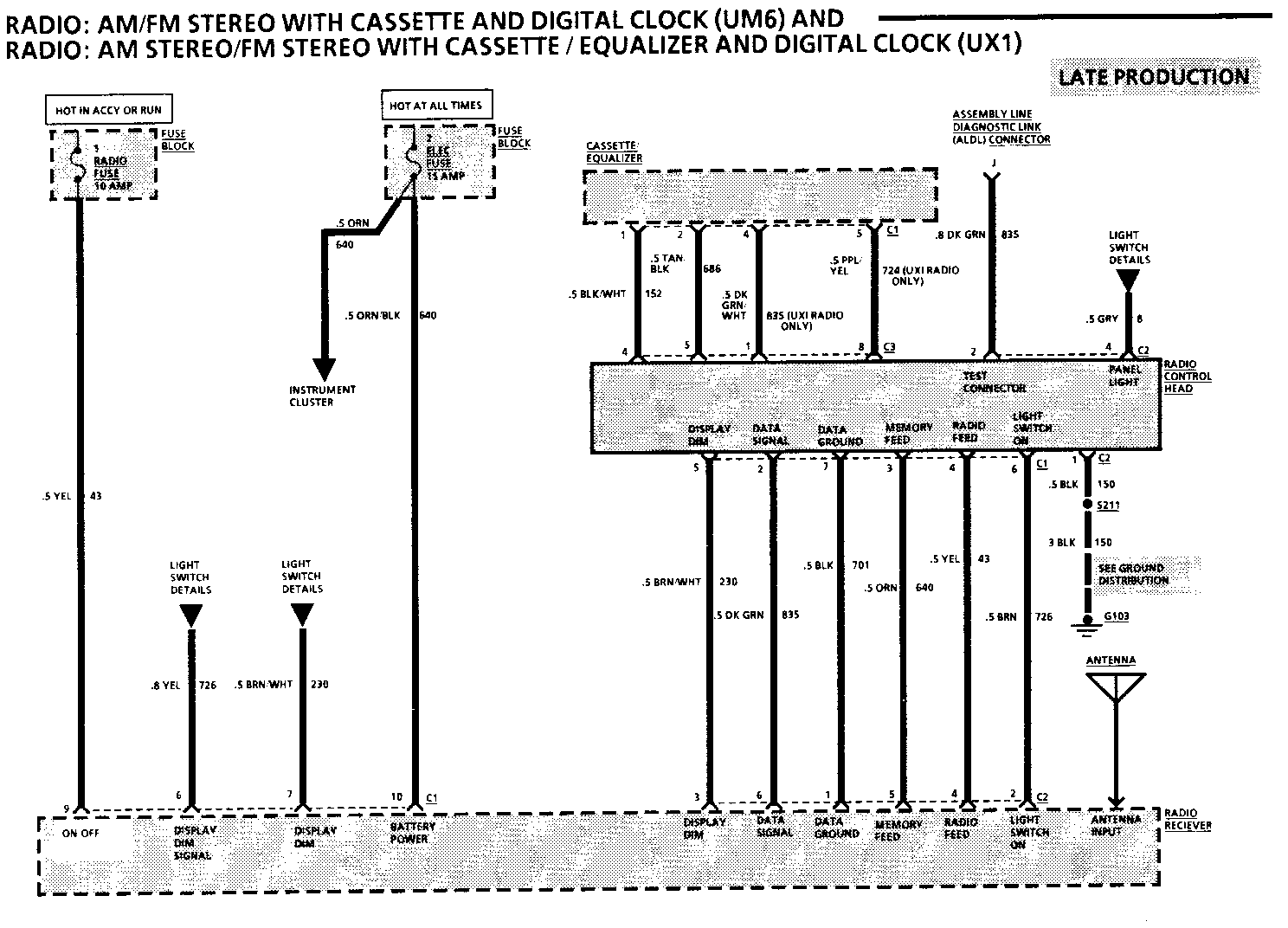
8A-12-0-A Light Switch Details 8A-33-2 Vehicle Speed Sensor 8A-110-1 Exterior Lights 8A-110-5 8A-134-0 Luggage Compartment Lid Release 8A-134-2 8A-134-3 8A-150-2-A Radio
VEHICLE SPEED SENSOR
TROUBLESHOOTING HINTS
Try the following check before doing the System Diagnosis.
1. Check the ECM Fuse and 3 ECM Fuse by visual inspection.
Go to System Diagnosis for diagnostic tests.
SYSTEM DIAGNOSIS
Do the tests listed for your symptom in the Symptom Table below.
Tests follow the Symptom Table.
SYMPTOM TABLE
SYMPTOM FOR DIAGNOSIS ------- ------------- Speedometer or any Do Test A other speed related function does not operate properly and ECM Code 24 is set
Speedometer or any Do Test B other speed related function does not operate properly and ECM Code 24 is not set
Speedometer is Do Test C inaccurate
If your symptom is not listed in the Symptom Table, perform all the tests.
A: VEHICLE SPEED SENSOR TEST
Measure: AC VOLTAGE
At: ELECTRONIC CONTROL MODULE (ECM) CONNECTOR C(GRY) (Disconnected)
Conditions:
Gear Selector: NEUTRAL
Raise car off the ground and turn drive wheels by hand while making measurement
Measure Correct For Between Voltage Diagnosis ------- ------- --------- C8 (YEL) & Varying from C2 (PPL) 0.1 to 0.5 See 1 volts AC
If the voltage is correct, replace Electronic Control Module.
1. Check YEL (400) and PPL (401) wires (see schematic). If wires are OK, replace Vehicle Speed Sensor.
B: ELECTRONIC CONTROL MODULE OUTPUT TEST (TABLE 1)
Measure: VOLTAGE
At: ELECTRONIC CONTROL MODULE (ECM) CONNECTOR B (WHT) (Disconnected)
Conditions:
Ignition Switch: RUN
Cruise Switch: ON
Raise car and rotate drive wheels while measuring voltage
Measure Correct For Between Voltage Diagnosis ------- ------- --------- Varing from B8 (DK GRN) less than 1 See 1 & Ground volt to more than 1.5 volts
If voltage is correct, go to Table 2.
1. Go to Table 3.
EXTERIOR LIGHTS
TROUBLESHOOTING HINTS
Turn Lights
If none of the Turn Lights come on:
Check TURN Fuse.
Check Turn Flasher, Turn/Hazard Switch, and related wiring.
If only one Turn Light doesn't flash, check that its ground is clean and tight.
Hazard Lights
If none of the Hazard Lights come on:
Check STOP Fuse by observing the Marker Lights.
Check Hazard Flasher, Turn/Hazard Switch, and related wiring.
If only one Hazard Light doesn't flash, check that its ground is clean and tight.
Stop Lights
If the Stop Lights do not come on:
Check STOP Fuse by operating Hazard Lights.
Check that the common ground is clean and tight.
Check Brake Switch, Turn/Hazard Switch, and related wiring.
High Level Stop Lights
If the High Level Stop Light does not come on:
Check STOP Fuse by operating Hazard Lights.
Check the Brake Switch adjustment by operating the Rear Brake Lights.
Check ground G303.
Front Park/Turn Lights
If the Front Park/Turn Lights do not come on:
Check TAIL Fuse. Check Park/Turn Relay. Check Bulbs and related wiring.
Front Marker Lights
If the Front Marker Lights do not come on:
Check TAIL Fuse. Check Bulbs and related wiring.
CIRCUIT OPERATION
Stop Lights
Voltage is applied directly from the Brake Switch to the High Level Stop Light.
The lower Stop Lights receive voltage through the WHT wire that feeds the Tum/Hazard Switch. With the switches in the position shown in the schematic, the Stop Lights are connected to the WHT wire through the YEL and DK GRN wires and the Turn Switches. They will come on when the Brake Switch is closed. Turn Lights
The lower Stop Lights also serve as the Rear Turn Lights. If the Turn Left Switches in the Turn/Hazard Switch are closed to the left, the left STOP/TURN Light comes on. The light gets battery voltage through the Turn Left Switch, and the YEL wire. The LH Turn Indicator also comes on.
Hazard Lights
If the Hazard switches are moved to the Hazard position, the Stop-Turn Lights will flash simultaneously. In this situation, power for all the lamps comes through the Hazard Flasher. The High Level Stop Light will not be operated by the Hazard Flasher.
Front Park/Turn Lights
With the Light Switch in HEAD or PARK, voltage is applied to the Front Marker Lights. Voltage is also applied to the Front Park/Turn Lights through the Park/Turn Relay and two resistance wires. The resistance of these wires is approximately 4 ohms. This causes the Front Park-Turn Light to light dimly. When a Turn Signal is operated, battery voltage from the Turn Hazard Switch Assembly is applied to the Front Park-Turn Light. The light flashes brightly.
LUGGAGE COMPARTMENT LID RELEASE
TROUBLESHOOTING HINTS
Try the following checks before doing the System Check.
1. Check the IGN Fuse by visual inspection.
2. Check that the Luggage Compartment Lid Release Solenoid case ground is clean and tight.
Go to System Check for a guide to normal operation.
Go to System Diagnosis for diagnostic tests.
SYSTEM CHECK
Use the System Check Table as a guide to normal operation.
SYSTEM CHECK TABLE
ACTION NORMAL RESULT ------ ------------- Press Luggage Luggage Compartment Compartment Release button with unlatches the Ignition Switch in RUN
Refer to System Diagnosis when a result is not normal.
SYSTEM DIAGNOSIS
Do the tests below if the Luggage Compartment Release does not operate prop- erly.
LUGGAGE COMPARTMENT RELEASE TEST (TABLE 1)
Measure: VOLTAGE
At: LUGGAGE COMPARTMENT RELEASE SOLENOID (Disconnected)
Condition:
Ignition Switch: RUN
Gear Selector: P (PARK)
Measure Correct For Between Voltage Diagnosis ------- ------- --------- BLK 0 Volts See 1 Ground
Luggage Compartment Release Button pressed (HOLD)
BLK & Battery See 1 Ground
If both voltages are correct, repair/replace the Luggage Compartment Release Solenoid.
1. Go to Table 2.
LUGGAGE COMPARTMENT RELEASE TEST (TABLE 2)
Measure: VOLTAGE
At: LUGGAGE COMPARTMENT RELEASE SWITCH CONNECTOR (Disconnected)
Conditions:
Ignition Switch: RUN
Gear Selector: P (PARK)
Luggage Compartment Release Solenoid: CONNECTED
Measure Correct For Between Voltage Diagnosis ------- ------- -------- A (LT GRN/ BLK) & Battery See 1 Ground A (LT GRN/ BLK) & Battery See 2 B(BLK)
If both voltages are correct, repair/replace the Luggage Compartment Release Switch.
1. Go to Table 3.
2. Check/repair the BLK (142) wire (see schematic).
LUGGAGE COMPARTMENT LID RELEASE
LUGGAGE COMPARTMENT RELEASE TEST (TABLE 3)
Connect: TEST LAMP
At: TRANSAXLE POSITION SWITCH (Connected)
Condition:
Gear Selector : P(PARK)
Measure Correct For Diagnosis Between Voltage Of Incorrect ------- ------- Results ------- C (LT GRN/ BLK Lamp lights See 1 & Ground
Gear Selector: Any position except P (PARK)
C(LT GRN/ Lamp does BLK) & not light See 2 Ground
If the test lamp indication is correct but the Luggage Compartment Release does not operate, check the BLK (142) and LT GRN/BLK (275) wires for an open (see schematic).
1. Check the BRN (250) wire for an open or adjust/replace the Transaxle Position Switch (see schematic).
2. Adjust/replace the Transaxle Position Switch.
CIRCUIT OPERATION
Battery voltage is applied at all times through the IGN Fuse to the Luggage Compartment Release Switch. With the Switch closed and the Transaxle Position Switch in PARK (Automatic Transaxle only), voltage is applied to the Lug- gage Compartment Release Solenoid, releasing the Luggage Compartment Lock.


General Motors bulletins are intended for use by professional technicians, not a "do-it-yourselfer". They are written to inform those technicians of conditions that may occur on some vehicles, or to provide information that could assist in the proper service of a vehicle. Properly trained technicians have the equipment, tools, safety instructions and know-how to do a job properly and safely. If a condition is described, do not assume that the bulletin applies to your vehicle, or that your vehicle will have that condition. See a General Motors dealer servicing your brand of General Motors vehicle for information on whether your vehicle may benefit from the information.
