SERVICE MANUAL UPDATE-SEC.6E2- 6E3 (CONVENIENCE CENTER I.D.)

SUBJECT: SERVICE MANUAL UPDATE - SECTION 6E3 (CONVENIENCE CENTER ID, DIAGNOSTIC GUIDELINES)
MODELS AFFECTED: 1990 REGAL
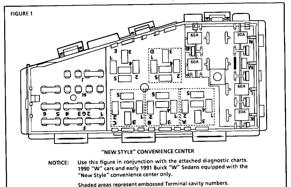
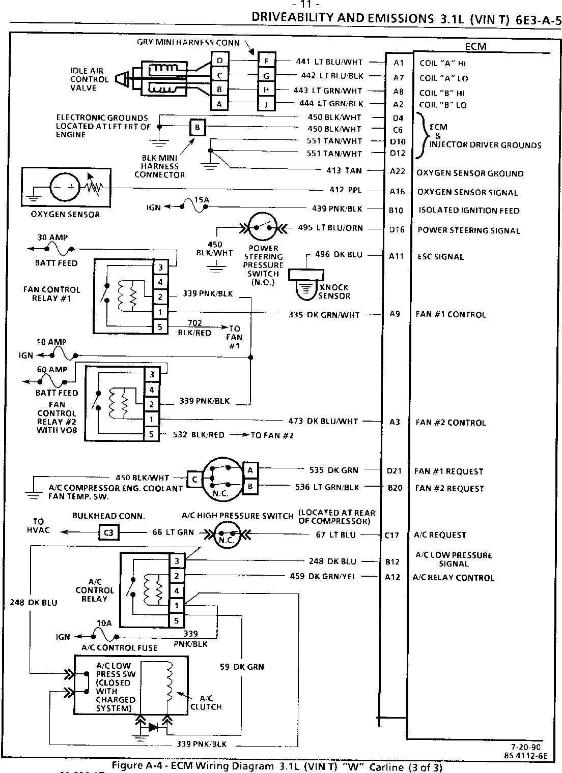
A/C CLUTCH CONTROL AND COOLING FAN CONTROL SUPPLEMENTAL DIAGNOSTIC GUIDELINES ----------------------------------------------------------------------------- Some late production 1990 Regals may be equipped with a new style convenience center that utilizes embossed terminal cavity numbers adjacent to each terminal cavity of the relay center (see Figure 1).
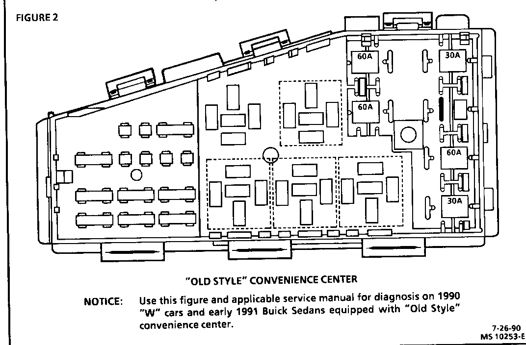
The old style unit does not utilize embossed numbers at the terminal cavities (see Figure 2). However, numbers were already assigned to the cavities in the diagnostic charts of the service manuals. The numbers were changed for the "new style" convenience center to comply with certain standards.
The circuits contained within the "new style" convenience center are in the same physical locations as those of the "old style" unit.
Diagnostic charts used in DRIVEABILITY AND EMISSIONS (SECTION 6E3) and ELECTRICAL DIAGNOSIS (SECTION 8A) may require probing or jumpering of the numbered terminal cavities as part of the diagnostic process. This is particularly true in diagnosis of the A/C clutch control and cooling fan control circuits.
If the vehicle is equipped with the "new style" convenience center (Figure 1), use the attached supplemental diagnostics that apply to the vehicle. If the vehicle is equipped with the "old style" convenience center (Figure 2), use the applicable Service Manual diagnostics.
The supplemental Service Manual pages are listed below:
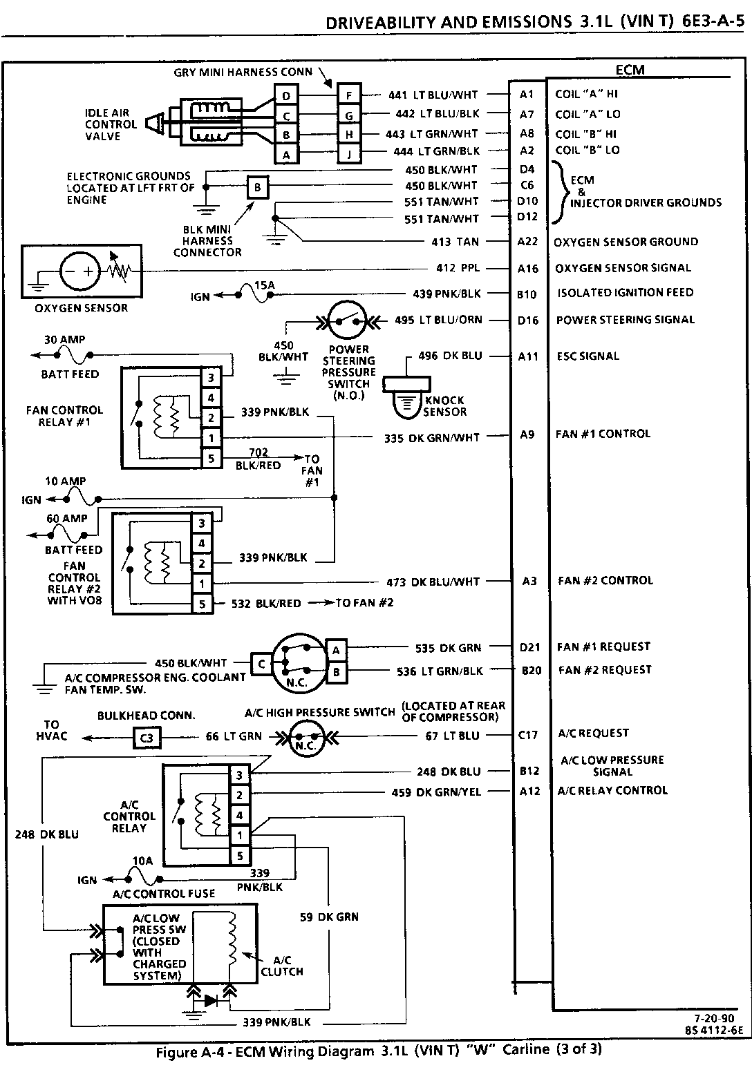
YEAR CARLINE ENGINE VIN PAGES ---- ------- ------ --- --------- 1990 Regal 3.1L T 6E3-A-5 6E3-C10-4 6E3-C12-2 6E3-C12-4
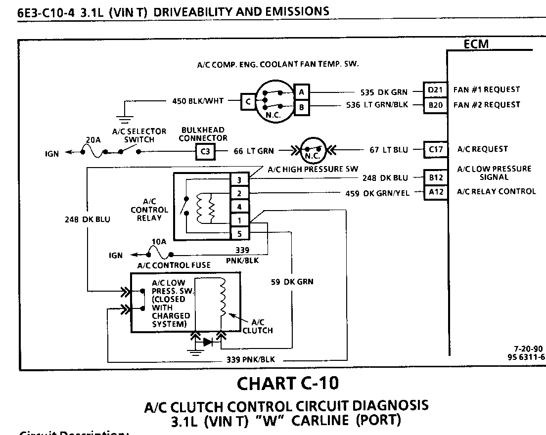
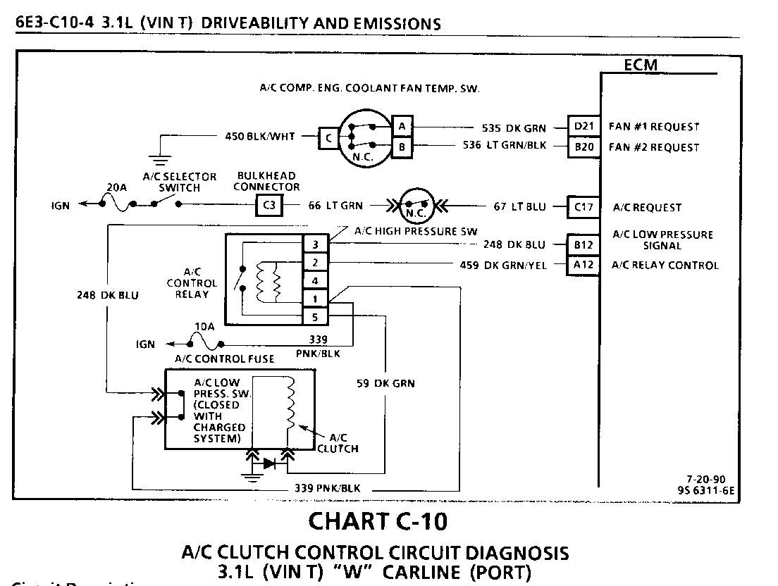
CHART C-1 0 A/C CLUTCH CONTROL CIRCUIT DIAGNOSIS 3.1L (VIN T) "W" CARLINE (PORT) ------------------------------------ Circuit Description: -------------------- The A/C clutch control relay is ECM controlled to delay A/C clutch engagement about .4 second after A/C is turned "ON." This allows the IAC to adjust engine rpm, before the A/C clutch engages. The ECM, also, causes the relay to disengage the A/C clutch during WOT, when high power steering pressure is present, or if engine is overheating. The A/C clutch control relay is energized, when the ECM provides a ground path for CKT 459. The low pressure switch will open, if A/C pressure is less than 40 psi (276 kPa). The high pressure switch will open, if A/C pressure exceeds about 440 psi (3034 kPa). The A/C pressure fan switch opens, when A/C pressure exceeds about 200 psi (1380 kPa).
Test Description: Numbers below refer to circled numbers on the diagnostic chart.
1. The ECM will only energize the A/C relay, when the engine is running. This test will determine if the relay, or CKT 459, is faulty.
2. In order for the clutch to properly be engaged, the low pressure switch must be closed to provide 12 volts to the relay, and the high pressure switch must be closed, so the A/C request (12 volts) will be present at the ECM.
3. Determines if the signal is reaching the ECM on CKTS 66 and 67 from the A/C control panel. Signal should only be present when the A/C mode or defrost mode has been selected.
4. A short to ground in CKT 66 and 67 can be the cause for A/C request not working.
5. If the ECM is seeing a high power steering pressure signal, the A/C clutch will be disengaged by the ECM.
6. With the engine idling and A/C "ON," the ECM should be grounding CKT 459, which should cause the test light to be "ON."
Diagnostic Aids:
If complaint was insufficient cooling, the problem may be caused by an inoperative cooling fan, or A/C pressure fan switch. The engine cooling fan should turn "ON," when A/C pressure exceeds a value to open the switch, which causes the ECM to energize the cooling fan relay. See CHART C-12 for cooling fan diagnosis. If fan operates correctly, see AIR CONDITIONING, (SECTION IB).
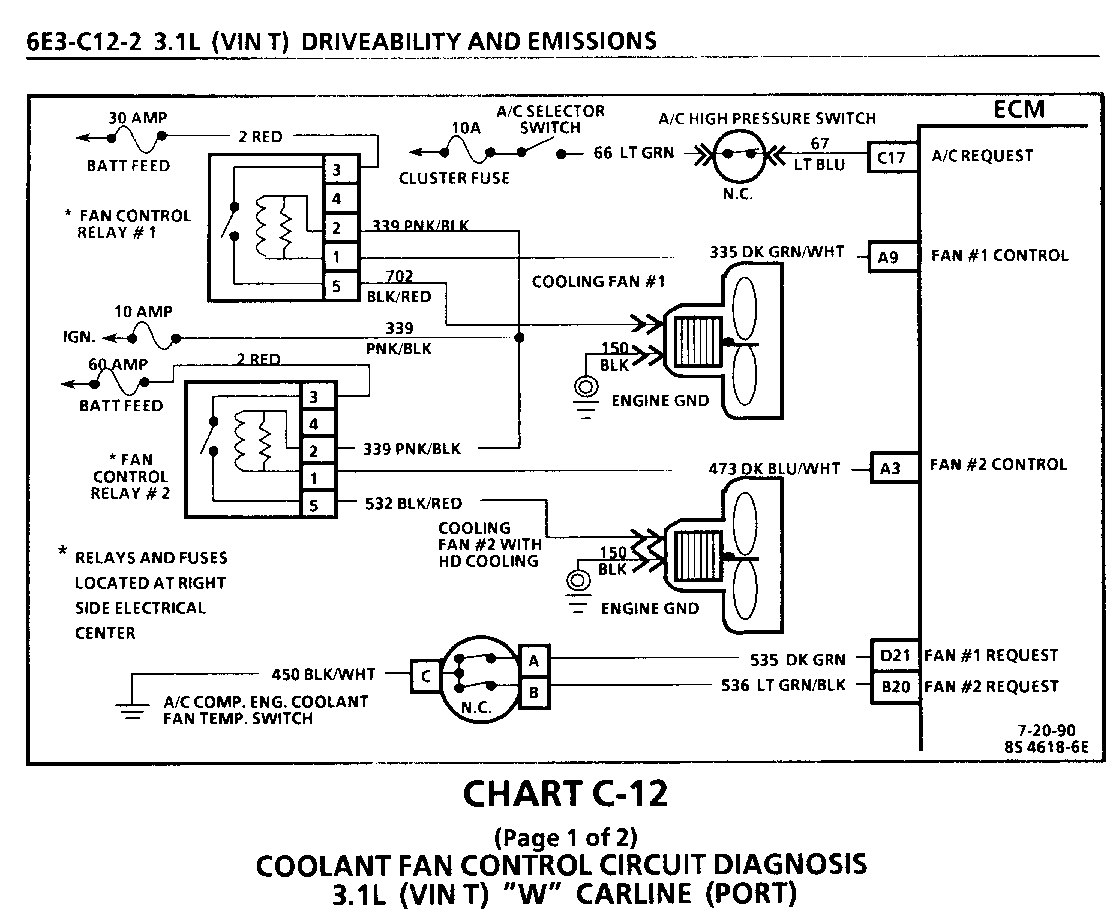
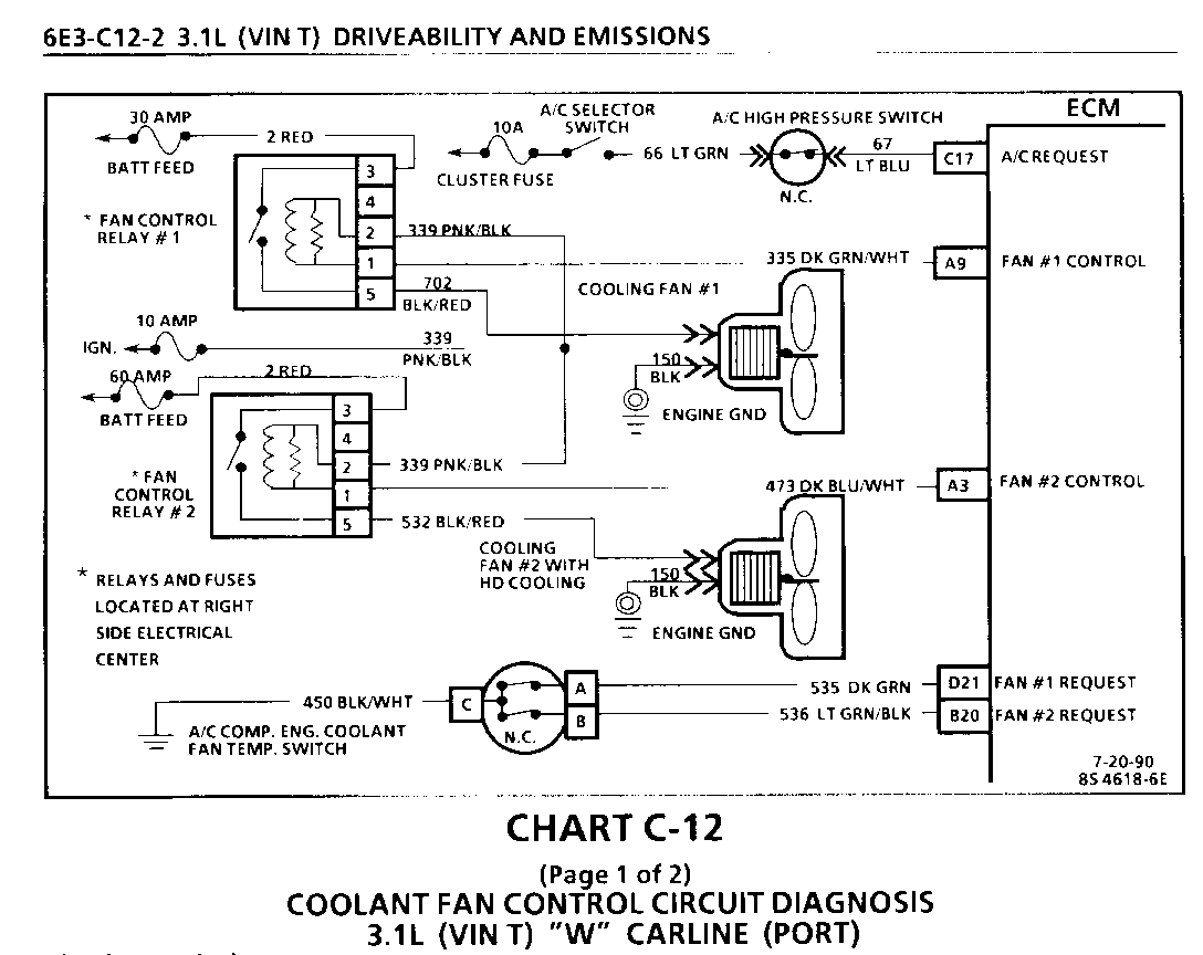
CHART C-1 2 (Page 1 of 2) COOLANT FAN CONTROL CIRCUIT DIAGNOSIS 3.1 L (VIN T) -W" CARLINE (PORT) --------------------------------------- Circuit Description: -------------------- The primary and secondary electric cooling fan(s) are controlled by the ECM, based on inputs from the coolant temperature sensor, the A/C control switches, vehicle speed and state of the A/C compressor engine coolant temperature switches. The ECM controls the fan(s) by grounding CKT 335 and/or CKT 473, which energizes the fan control relay. Battery voltage is then supplied to the fan motor.
The ECM grounds CKT 335 and/or CKT 473, when coolant temperature is over about 1060C (223 degrees F), or when A/C has been requested, and the fan control switch(es) open with high A/C pressure, about 200 psi (1380 kPa). Once the ECM turns the relay "ON," it will keep it "ON" for a minimum of 30 seconds, or until vehicle speed exceeds 70 mph (40 mph for secondary fan).
Also, if Code 14 or 15 sets, or the ECM is in throttle body back up, the primary fan will run at all times.
Test Description: Numbers below refer to circled numbers on the diagnostic chart.
1. With the diagnostic terminal grounded, the cooling fan control driver(s) will close, which should energize the fan control relay(s).
2. If the A/C fan control switch or circuit is open, the fan would run whenever A/C is requested.
3. With A/C clutch engaged, the A/C fan control switches should open, when A/C intermediate pressure exceeds about 200 psi (1380 kPa). This signal should cause the ECM to energize the fan control relay(s).
Diagnostic Aids:
If the owner complained of an overheating problem, it must be determined if the complaint was due to an actual boil over, or the hot light, or temp. gage indicated over heating.
If the gage, or light, indicates overheating, but no boil over is detected, the gage circuit should be checked. The gage accuracy can, also, be checked by comparing the coolant sensor reading using a "Scan" tool and comparing its reading with the gage reading.
If the engine is actually overheating, and the gage indicates overheating, but the cooling fan is not coming "ON," the coolant sensor has probably shifted out of calibration and should be replaced.
If the engine is overheating, and the cooling fan is "ON," the cooling system should be checked.
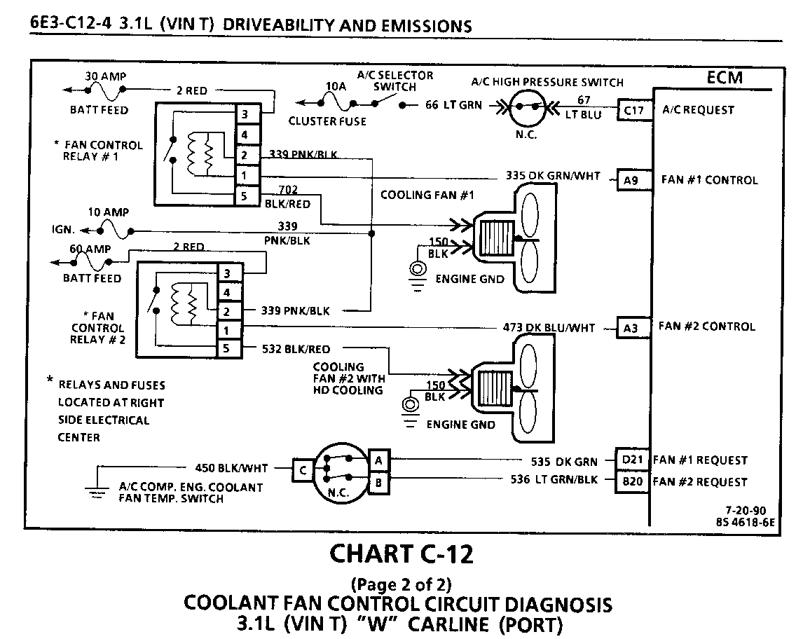
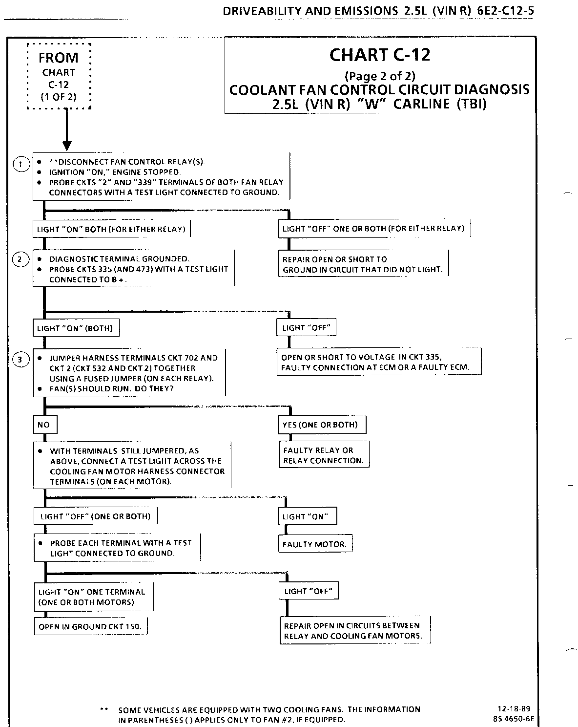
CHART C-1 2 (Page 2 of 2) COOLANT FAN CONTROL CIRCUIT DIAGNOSIS 3.1 L (VIN T) "W" CARLINE (PORT) ------------------------------------- Test Description: Numbers below refer to circled numbers on the diagnostic chart.
1. 12 volts should be available to CKT 339 and CKT 2 on each relay when the ignition is "ON."
2. This test checks the ability of the ECM to ground CKT 335 (CKT 473).
The "Service Engine Soon" light should also be flashing at this point. If it isn't flashing, see CHART A-2.
3. If the fan does not turn "ON" at this point, CKT 702 (535) or CKT 150 is open, or the cooling fan motor(s) are faulty.
General Motors bulletins are intended for use by professional technicians, not a "do-it-yourselfer". They are written to inform those technicians of conditions that may occur on some vehicles, or to provide information that could assist in the proper service of a vehicle. Properly trained technicians have the equipment, tools, safety instructions and know-how to do a job properly and safely. If a condition is described, do not assume that the bulletin applies to your vehicle, or that your vehicle will have that condition. See a General Motors dealer servicing your brand of General Motors vehicle for information on whether your vehicle may benefit from the information.
