SERVICE MANUAL UPDATE-SEC. 10 POWER WINDOW/DOOR SWITCH ASSY

VEHICLES AFFECTED: 1990 BUICK W
The following procedures have been revised from the 1990 Buick Regal Service Manual. Please use the following procedures for removing or installing the power window and door switch assembly and/or the trim panel.
POWER WINDOW AND DOOR SWITCH ASSEMBLY
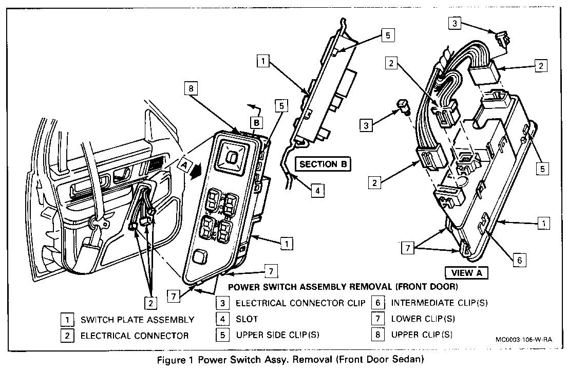
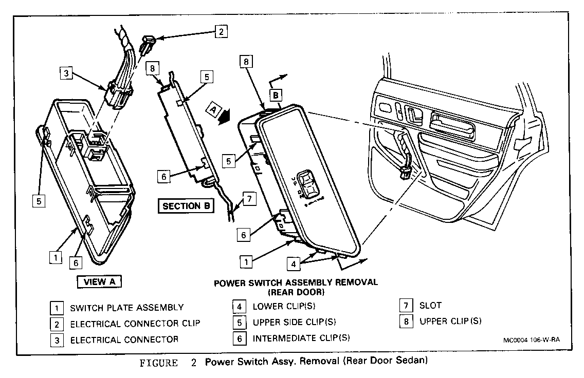
SEDAN - Figures 1 and 2
NOTICE: WHEN REMOVING A DOOR TRIM PANEL OR SWITCH PLATE, THE IGNITION SWITCH MUST BE IN THE OFF POSITION. THIS WILL ELIMINATE THE POSSIBILITY OF SHORTING OUT THE SWITCH IF A SCREWDRIVER, AWL, OR METAL OBJECT IS USED TO REMOVE THE SWITCH FROM THE HARNESS.
REMOVE OR DISCONNECT
1. Switch assembly by prying lower clips, using a putty knife, through slot in trim panel at bottom of switch housing.
*Lift lower part of switch assembly from housing using hand.
2. Lower clips using a nylon spatula.
*Slide spatula between side of switch assembly and housing, pry loose.
3. Upper clips
* Remove from assembly
4. Connectors
INSTALL OR CONNECT
1. Connectors
2. Upper clips to switch assembly
* Rebend to original shape and slide into position
3. Switch assembly to trim panel
* Press into position with hand.
TRIM PANEL
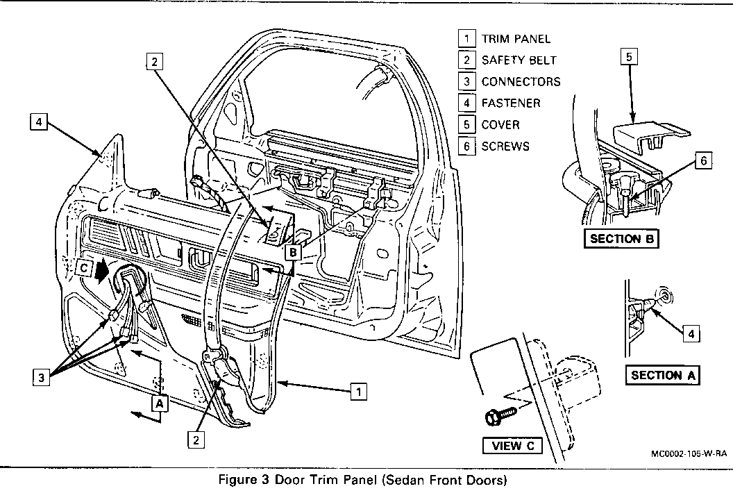
COUPE AND SEDAN FRONT DOORS
Tool Required: J-24595-C Door Trim and Garnish Clip Remover
Figure 3
REMOVE OR DISCONNECT
1. Escutcheon cover
2. Screws and safety belt from shoulder belt escutcheon
3. Pull handle screws
4. Retractor cover. Refer to "Passive Restraint Belt Retractor cover - Coupe and Sedan Front Door" in this section.
*Install hand bezel. Refer to "Inside Hand Bezel" in this section.
5. Power window switch assembly, if present. Refer to "Power Window and Door Switch assembly" in this section.
6. Bracket screw to door, Sedan only
* Removable through switch cutout in housing.
7. Window regulator, if present
8. Screw from trim panel, Coupe only
9. Door trim panel using J-24595-C to disengage fasteners on trim panel from holes in door inner panel.
INSTALL OR CONNECT
1. Wire harness, if present, through openings in trim panel.
2. Trim panel to door by aligning fasteners on trim panel to holes in door inner panel and pressing trim panel to door until fasteners are fully engaged.
3. Screw to trim panel, Coupe only.
4. Bracket screw to door by aligning bracket on housing to hole in sheet metal and drive screw through switch cutout in housing, Sedan only.
5. Window regulator, if removed.
6. Power window and door switch assembly, if removed. Refer to "Power Window and Door Switch Assembly" in this section.
7. Retractor cover. Refer to "Passive Restraint Belt Retractor cover - Coupe and Sedan Front Doors" in this section.
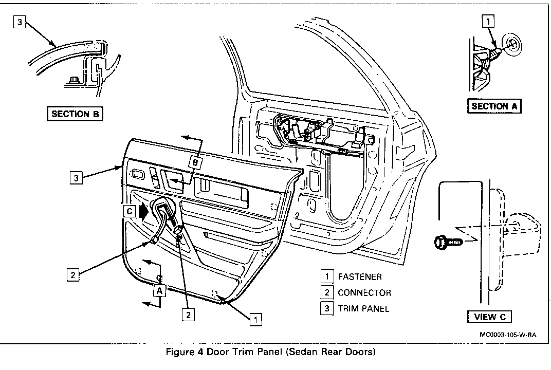
SEDAN REAR DOORS Figure 4
REMOVE OR DISCONNECT
1. Screws from pull handle bezel
2. Inside handle bezel. Refer to "Inside Hand Bezel" in this section.
3. Power window and door switch assembly, if present. Refer to "Power Window and Door Switch Assembly", if present. Refer to "Power Window and Door Switch Assembly Front Door" in this section.
4. Bracket screw to door.
* Removable through switch cutout in housing.
5. Window regulator handle, if present.
6. Lamp form armrest cutout, if present.
7. Door trim panel, using J-24595-C to disengage fasteners on trim panel from holes in door inner panel.
INSTALL OR CONNECT
1. Wire harness, if present, through opening in trim panel and armrest cutout.
2. Trim panel to door by tucking under retainer on inner panel and aligning fasteners on trim panel to holes in door inner panel. Apply sufficient pressure to snap Easteners into place.
3. Lamp to cutout, if present.
4. Bracket screw to door by aligning bracket on housing to hole in sheet metal and drive screw through switch cutout in housing to secure.
5. Window regulator, if present.
6. Power window switch assembly. Refer to "Power Window and Door Switch Assembly Front Door", in this section.
7. Inside handle bezel. Refer to "Inside Handle Bezel" in this section.
8. Screws to pull handle bezel.


General Motors bulletins are intended for use by professional technicians, not a "do-it-yourselfer". They are written to inform those technicians of conditions that may occur on some vehicles, or to provide information that could assist in the proper service of a vehicle. Properly trained technicians have the equipment, tools, safety instructions and know-how to do a job properly and safely. If a condition is described, do not assume that the bulletin applies to your vehicle, or that your vehicle will have that condition. See a General Motors dealer servicing your brand of General Motors vehicle for information on whether your vehicle may benefit from the information.
