SERVICE MANUAL UPDATE-SEC. 8A STEERING WHEEL CONTROLS

SUBJECT: SERVICE MANUAL UPDATE SECTION 8A STEERING WHEEL CONTROLS (NEW SCHEMATICS AND DIAGNOSTICS)
VEHICLES AFFECTED: 1990 PONT, OLDS, BUICK 'W' MODELS
There was a mid Production change in the 1990 steering column wiring. Please note the following changes to your copies of the 1990 Service Manuals. BUICK Old Page Remove ----- New Page Add --------------- ------------ 8A-11-4 8A-11-4 8A-89-1a 8A-89-lb 8A-89-7 8A-89-7 8A-89-10a 8A-89-10b 8A-89-10c
OLDSMOBILE
8A-11-4 8A-11-4 8A-89-la 8A-89-lb 8A-89-7 8A-89-7 8A-89-10a 8A-89-10b 8A-89-10c
PONTIAC
8A-11-2 8A-11-2 8A-89-lA 8A-89-lb 8A-89-7 8A-89-10a 8A-89-10b 8A-89-10c
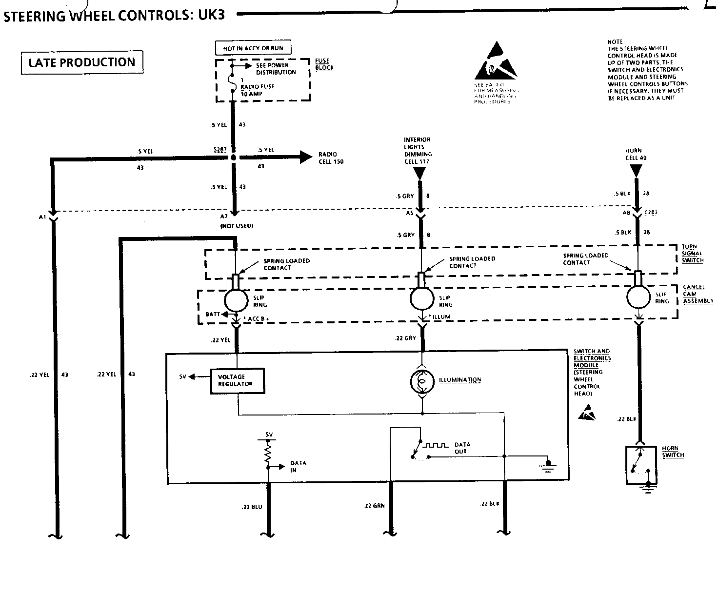
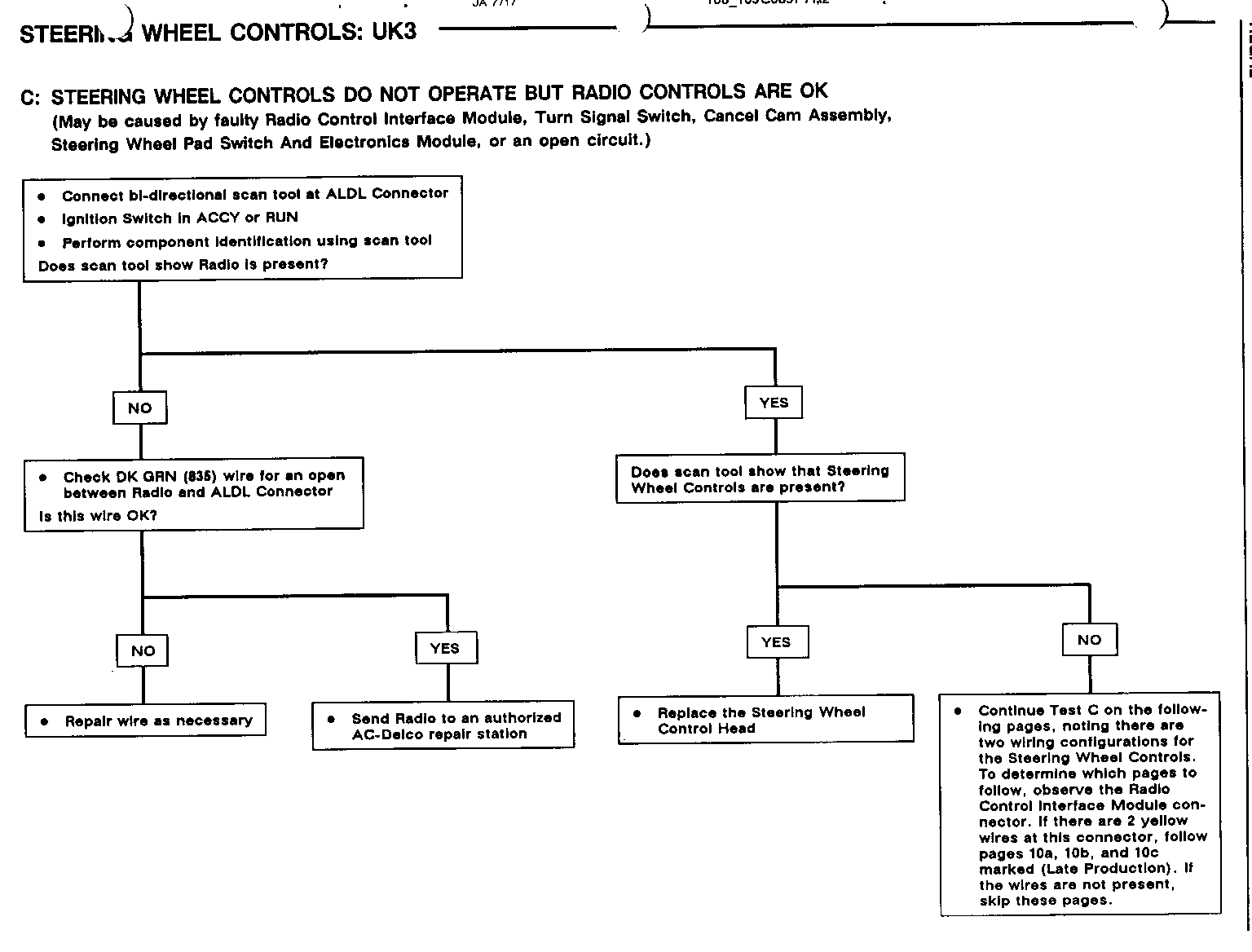
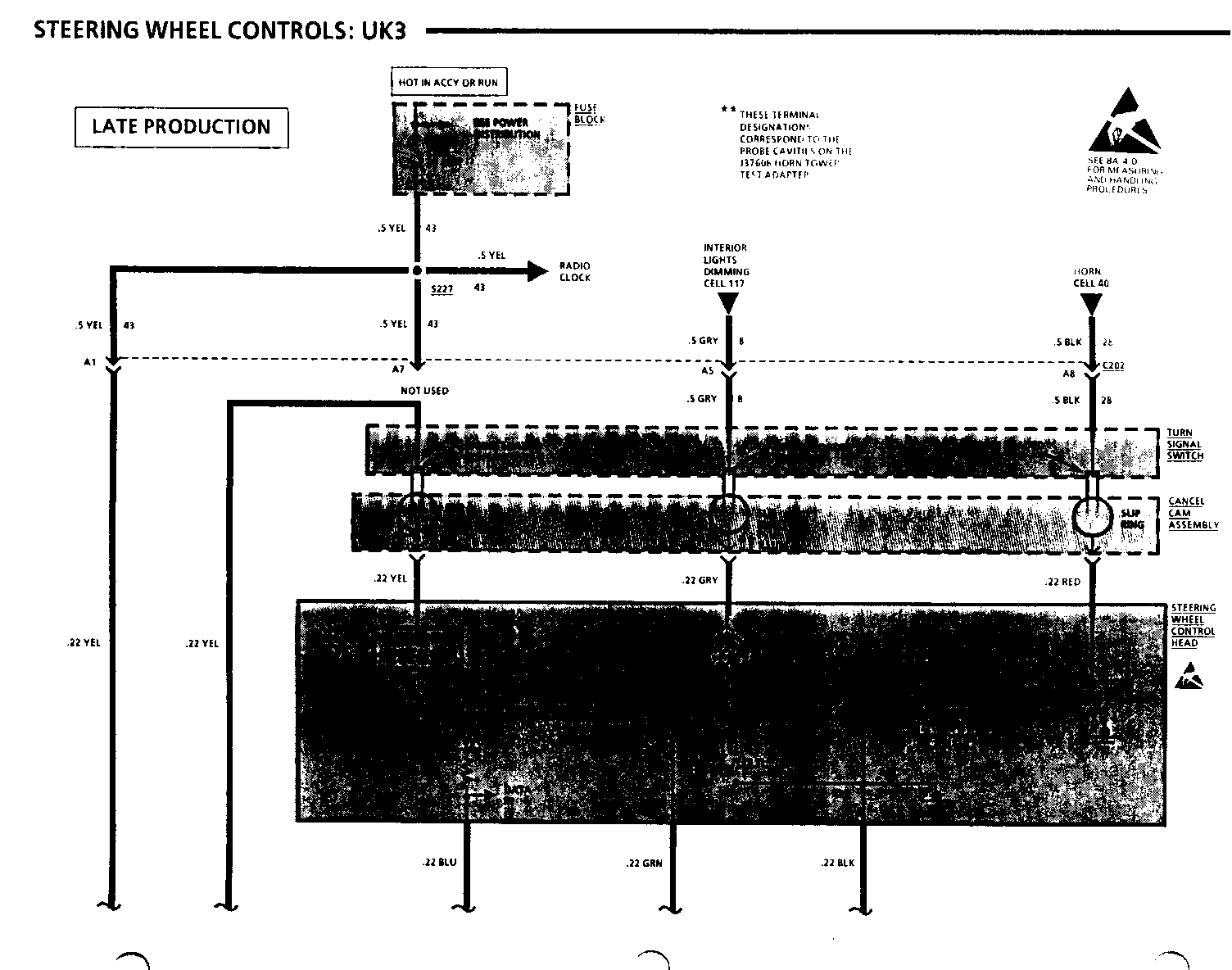
STEERING WHEEL CONTROLS: UK3
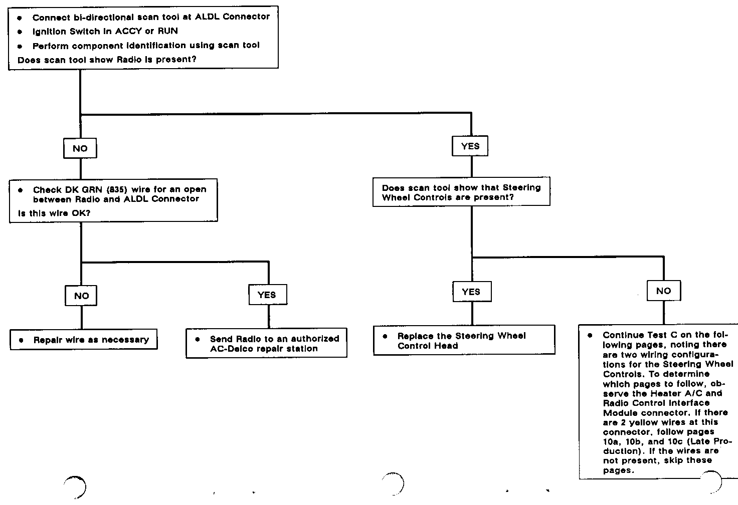
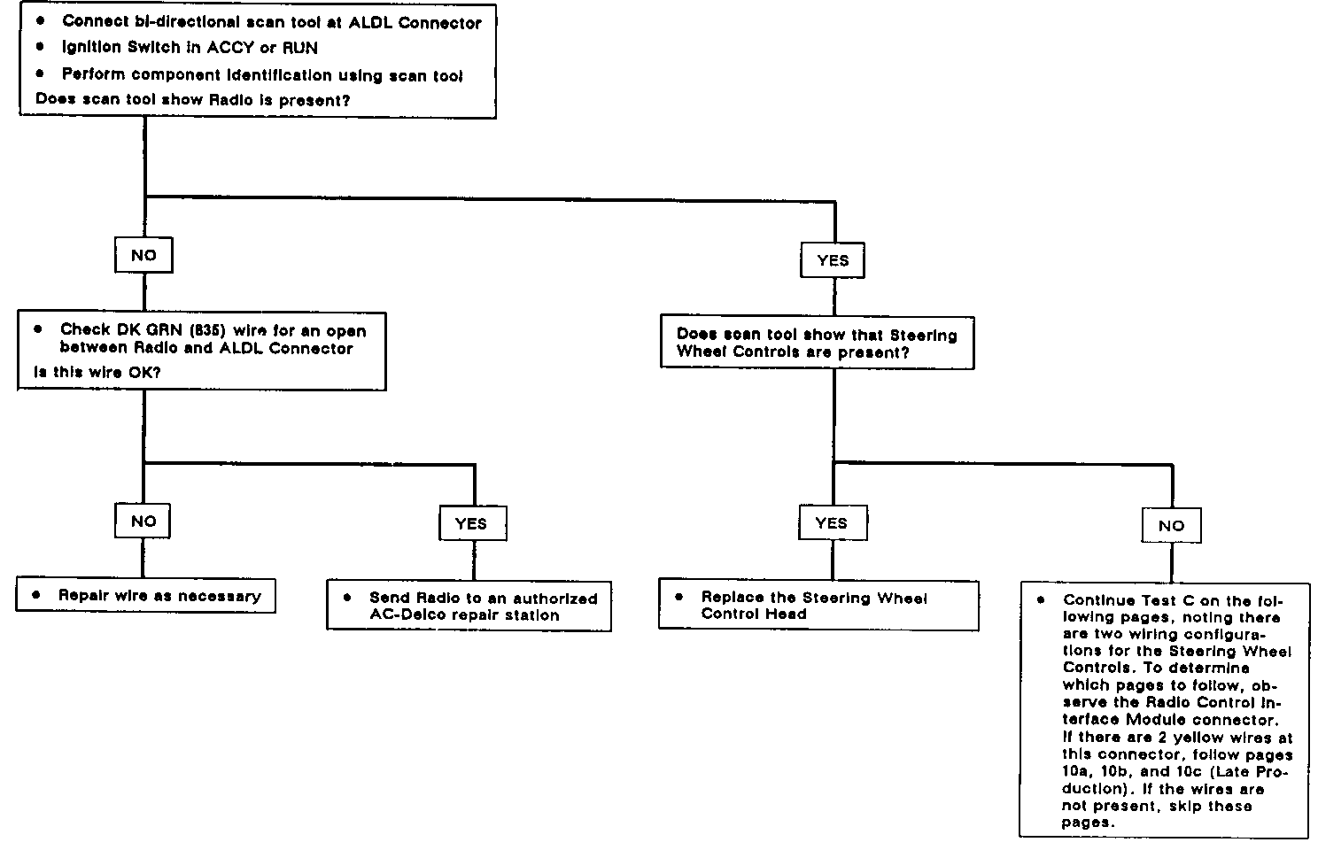
C: STEERING WHEEL CONTROLS DO NOT OPERATE BUT RADIO CONTROLS ARE OK
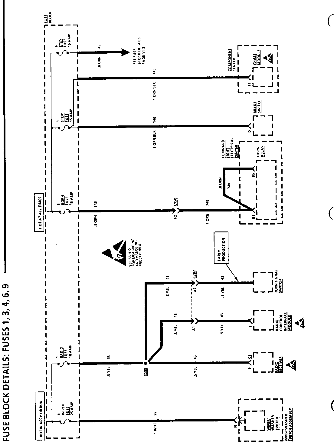
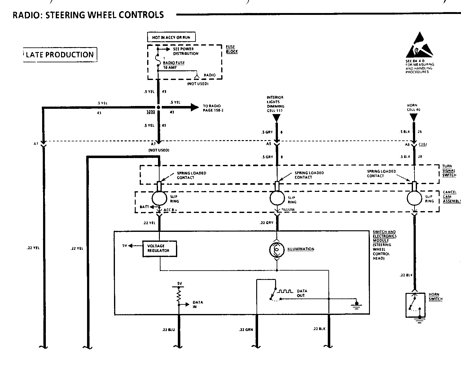
(May be caused by faulty Radio Control Interface Module, Turn Signal Switch, Cancel Cam Assembly, Steering Wheel Pad Switch And Electronics Module, or an open circuit.)
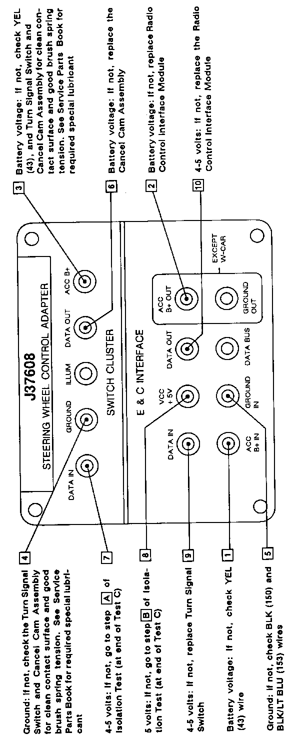
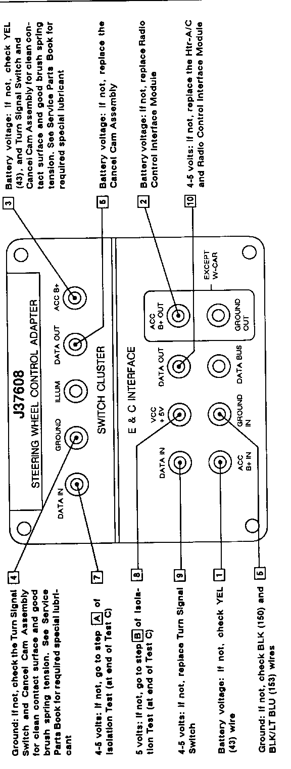
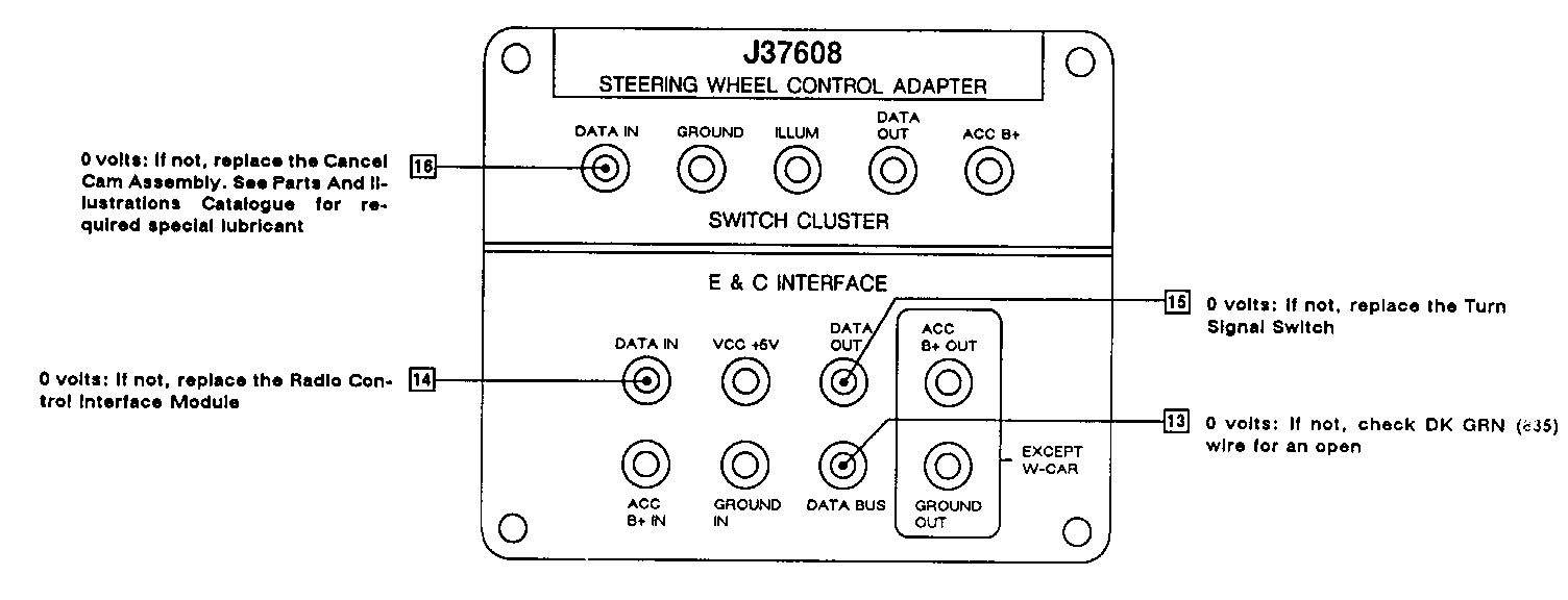
- J37608 Steering Wheel Control Adapter connected (see Fig. 1)
- Ignition Switch in RUN
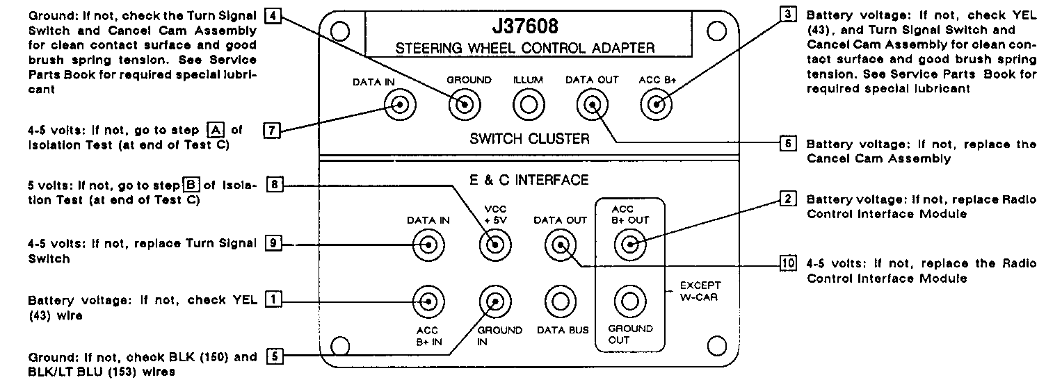
- Measure voltage at terminal probe cavities in numerical order ([1], [2], [3], etc.)
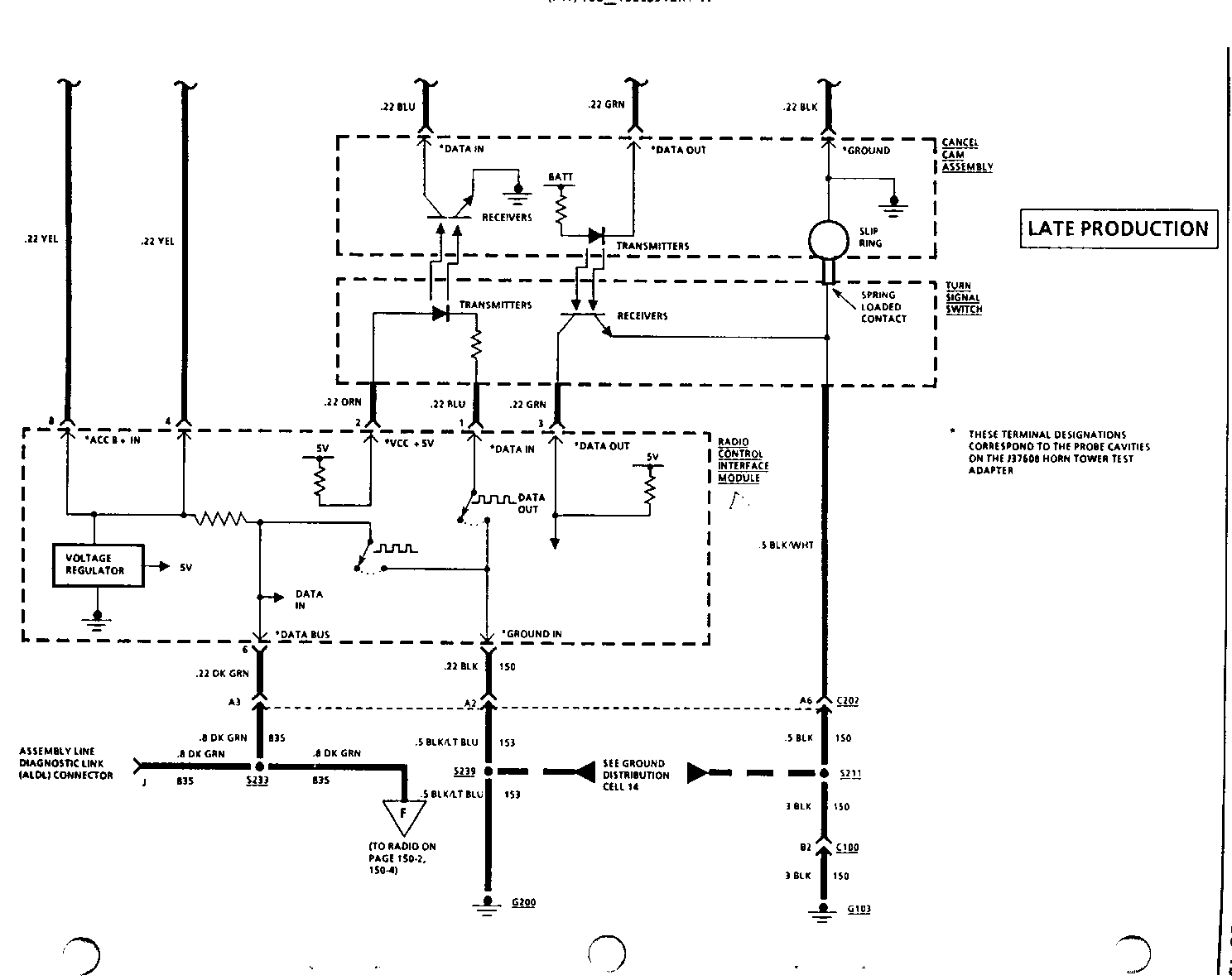
- J37608 probe terminals agree with schematic labels. For example, "DATA IN" on the SWITCH CLUSTER side of J37608 is the same as "DATA IN" on the Turn Signal Cancel Cam Assembly on the schematic
Test Explanation: Steps [1], [2], [3], [4] and [5] verify that corres- ponding power or ground circuits are OK
Step [6] verifies Cancel Cam Assembly Internal continuity by checking for voltage
Step [7] verifies Steering Wheel Control Head "DATA IN" continuity
Step [8] verifies Radio Control Interface Module Voltage regulation circuit
Step [9] verifies Turn Signal Switch Transmitter Internal continuity by checking for voltage
Step [10] verifies Radio Control Interface Module "DATA IN" circuit continuity
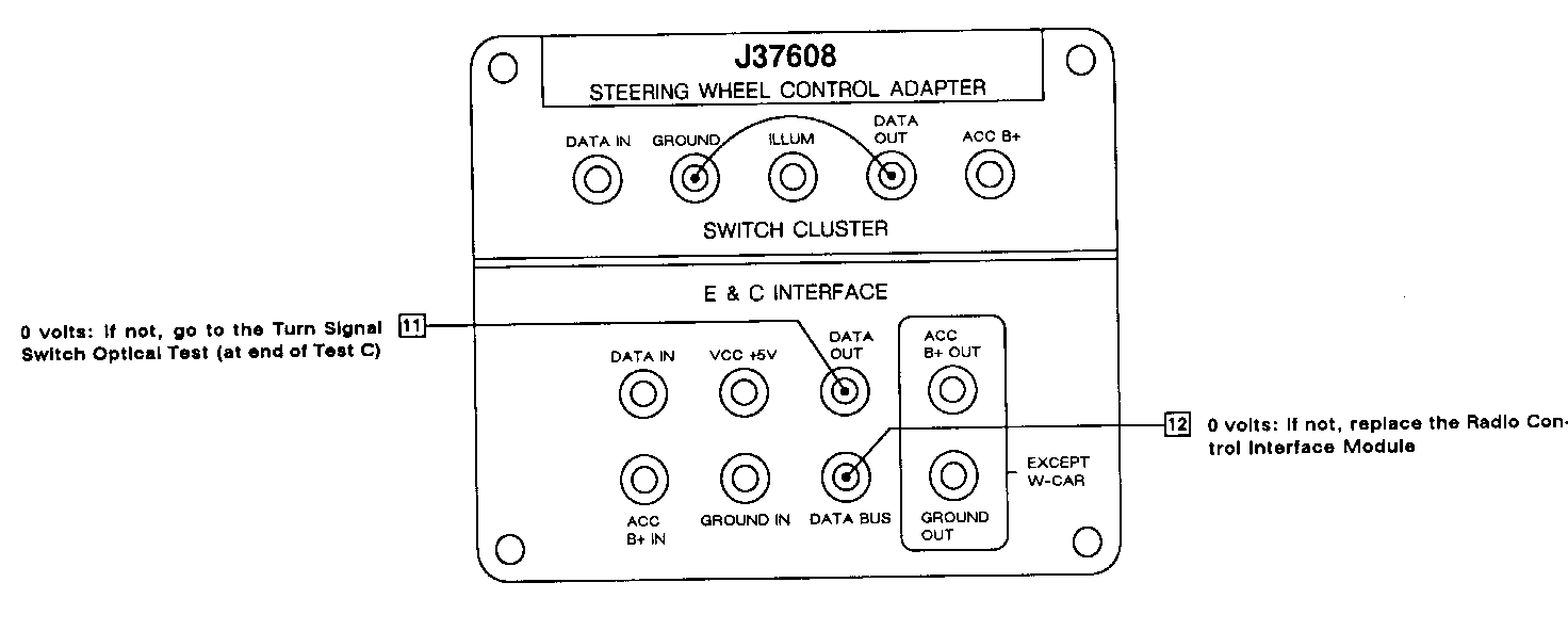
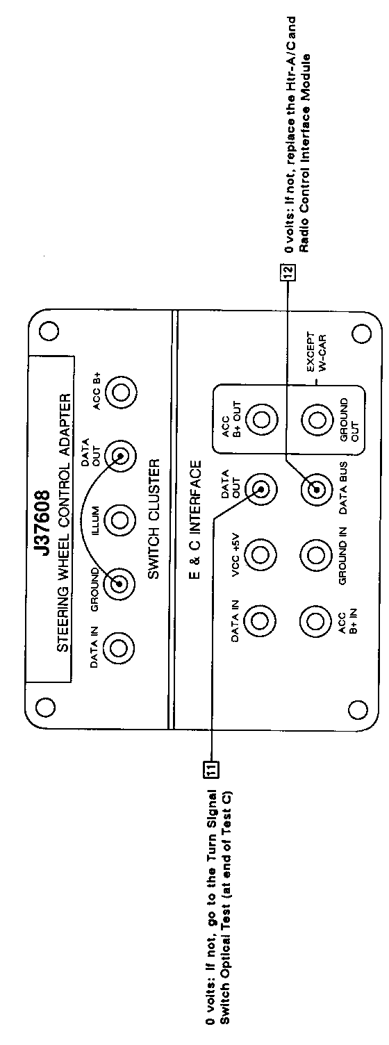
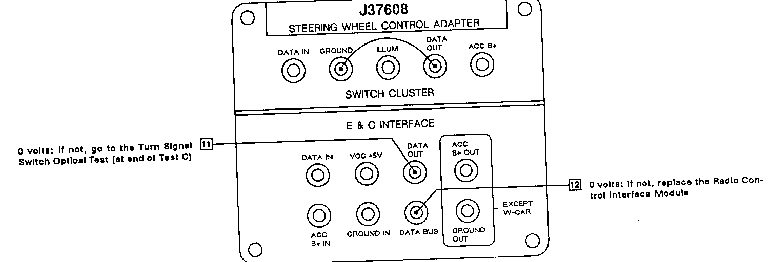
- Jumper J37608 SWITCH CLUSTER terminals "DATA OUT" and "GROUND" as shown
- Measure in numerical order
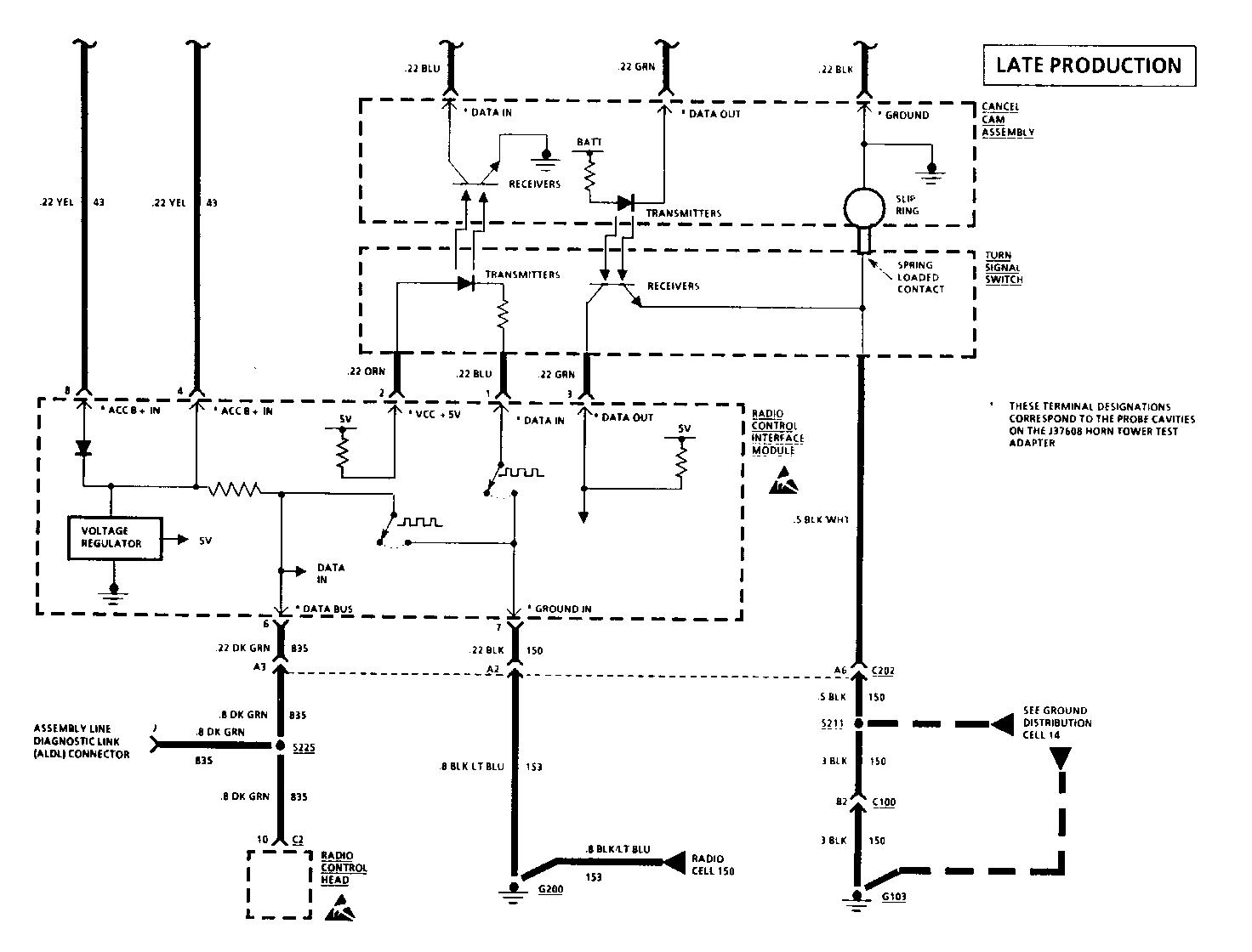
Test Explanation: The jumper simulates a ground signal from the Steering Wheel Control Head. If the Cancel Cam Assembly transmitters and Turn Signal Switch receivers are operating, a ground signal will be transmitted through the optical slip ring and will be measured at the J37608 E & C INTERFACE probe cavity "DATA OUT". If the Radio Control Interface Module is OK, the ground signal will be sent through the Radio Control Interface Module and will appear at the J37608 E & C INTERFACE "DATA BUS" cavity.
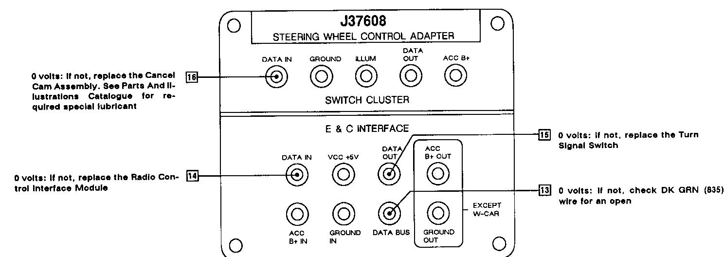
- Disconnect jumper from the previous step
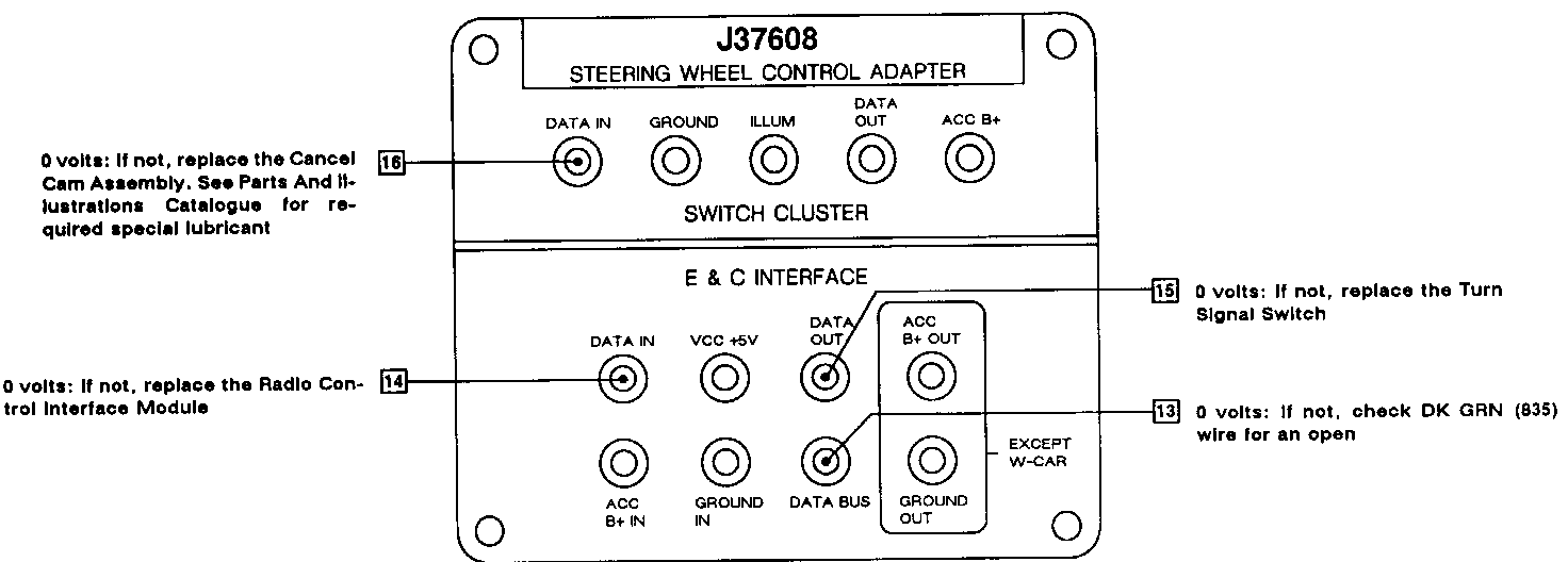
- Jumper ALDL terminal J (DK GRN) to ground
- Measure in numerical order
Test Explanation: The jumper ALDL terminal J simulates a data signal from the Radio. If the DKGRN (835) wire is OK, a ground signal will appear at the J37608 "DATA BUS" terminal. If the Radio Control Interface Module is OK, a ground signal will appear at the J37608 E & C INTERFACE "DATA IN" cavity. If the Turn Signal Switch transmitters are operating, the ground signal will appear at the E & C INTERFACE "DATA OUT" cavity. If the Cancel Cam Assembly receivers are OK, the ground signal will appear at the SWITCH CLUSTER "DATA IN" cavity. If all signals are good, Steering Wheel Control Head must be at fault.
(May be caused by faulty Radio Control Interface Module, Turn Signal Switch, Cancel Cam Assembly, Steering Wheel Pad Switch And Electronics Module, or an open circuit).
- J37608 Steering Wheel Control Adapter connected
- Ignition Switch is RUN
- Measure voltage at terminal probe cavities in numerical order ([1], [2], [3], etc.)
- J37608 probe terminals agree with schematic labels. For example, "DATA IN" on the SWITCH CLUSTER side of J37608 is the same as "DATA IN" on the Turn Signal Cancel Cam Assembly on the schematic
Test Explanation: Steps [1],[2], [3], [4] and [5] verify that corresponding power or ground circuits are OK
Step [6] verifies Cancel Cam Assembly Internal continuity by checking for voltage
Step [7] verifies Steering Wheel Control Head "DATA IN" continuity
Step [8] verifies Htr - A/C and Radio Control Interface Module Voltage regulation circuit
Step [9] verifies Turn Signal Switch Transmitter Internal continuity by checking for voltage
Step [10] verifies Htr - A/C and Radio Control Interface Module "DATA IN" circuit continuity
- Jumper J37608 SWITCH CLUSTER terminals "DATA OUT" and "GROUND" as shown
- Measure in numerical order
Test Explanation: The jumper simulates a ground signal from the Steering Wheel Control Head. If the Cancel Cam Assembly transmitters and Turn Signal Switch receivers are operating, a ground signal will be transmitted through the optical slip ring and will be measured at the J37608 E & C INTERFACE probe cavity "DATA OUT". If the Htr-A/C and Radio Control Interface Module is OK, the ground signal will be sent through the Htr-A/C and Radio Control Interface Module and will appear at the J37608 E & C INTERFACE "DATA BUS" cavity.
- Disconnect jumper from the previous step
- Jumper ALDL terminal J (DK GRN) to ground
- Measure in numerical order
Test Explanation: The jumper at ALDL terminal J simulates a data signal from the Radio. If the DKGRN (835) wire is OK, a ground signal will appear at the J37608 "DATA BUS" terminal. If the Htr-A/C and Radio Control Interface Module is OK, a ground signal will appear at the J37608 E & C INTERFACE "DATA IN" cavity. If the Turn Signal Switch transmitters are operating, the ground signal will appear at the E & C INTERFACE "DATA OUT" cavity. If the Cancel Cam Assembly receivers are OK, the ground signal will appear at the SWITCH CLUSTER "DATA IN" cavity. If all signals are good, Steering Wheel Control Head must be at fault.
(May be caused by faulty Radio Control Interface Module, Turn Signal Switch, Cancel Cam Assembly, Steering Wheel Pad Switch And Electronics Module, or an open circuit.)
- J37608 Steering Wheel Control Adapter connected
- Ignition Switch is RUN
- Measure voltage at terminal probe cavities in numerical order ([1], [2], [3], etc.)
- J37608 probe terminals agree with schematic labels. For example, "DATA IN" on the Turn Signal Cancel Cam Assembly on the schematic
Test Explanation: Steps [1],[2], [3], [4] and [5] verify that corresponding power or ground circuits are OK
Step [6] verifies Cancel Cam Assembly Internal continuity by checking for voltage
Step [7] verifies Steering Wheel Control Head "DATA IN" continuity
Step [8] verifies Radio Control Interface Module Voltage regulation circuit
Step [9] verifies Turn Signal Switch Transmitter Internal continuity by checking for voltage
Step [10] verifies Radio Control Interface Module "DATA IN" circuit continuity
(May be caused by faulty Radio Control Interface Module, Turn Signal Switch, Cancel Cam Assembly, Steering Wheel Pad Switch And Electronics Module, or an open circuit.)
- Jumper J37608 SWITCH CLUSTER terminals "DATA OUT" and "GROUND" as shown
- Measure in numerical order
Test Explanation: The jumper simulates a ground signal from the Steering Wheel Control Head. If the Cancel Cam Assembly trans- mitters and Turn Signal Switch receivers are operating, a ground signal will be transmitted through the optical slip ring and will be measured at the J37608 E & C INTERFACE probe cavity "DATA OUT". If the Radio Control Interface Module is OK, the ground signal will be sent through the Radio Control Interface Module and will appear at the J37608 E & C Interface "DATA BUS" cavity.
- Disconnect jumper from the previous step
- Jumper ALDL terminal J (DK GRN) to ground
- Measure in numerical order
Test Explanation: The jumper at ALDL terminal J simulates a data signal from the Radio. If the DKGRN (835) wire is OK, a ground signal will appear at the J37608 "DATA BUS" terminal. If the Radio Control Interface Module is OK, a ground signal will appear at the J37608 E & C INTERFACE "DATA IN" cavity. If the Turn Signal Switch transmitters are operating, the ground signal will appear at the E & C INTERFACE "DATA OUT" cavity. If the Cancel Cam Assembly receivers are OK, the ground signal will appear at the SWITCH CLUSTER "DATA IN" cavity. If all signals are good, Steering Wheel Control Head must be at fault.
General Motors bulletins are intended for use by professional technicians, not a "do-it-yourselfer". They are written to inform those technicians of conditions that may occur on some vehicles, or to provide information that could assist in the proper service of a vehicle. Properly trained technicians have the equipment, tools, safety instructions and know-how to do a job properly and safely. If a condition is described, do not assume that the bulletin applies to your vehicle, or that your vehicle will have that condition. See a General Motors dealer servicing your brand of General Motors vehicle for information on whether your vehicle may benefit from the information.
