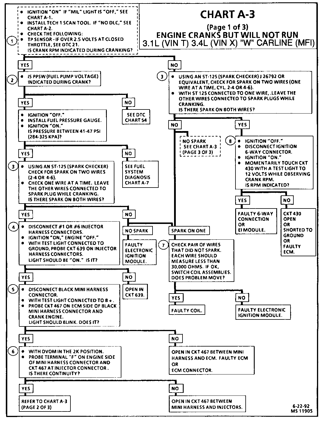
SER. MAN. UPDATE SEC. 6E3-A ENGINE CRANKS WILL NOT RUN

SUBJECT: SERVICE MANUAL UPDATE - SECTION 6E3-A REVISED CHART A-3
VEHICLES AFFECTED: 1991-92 "W" MODELS WITH 3.1 L (VIN T, RPO LHO) AND 3.4L (VIN X, RPO LQ1) ENGINES
This Bulletin contains revisions to Section 6E3 of the 1991-92 "W" Carline Service Manuals.
The 3.1 L (LHO) and 3.4L (LQ1) Engine Cranks But Will Not Run (Chart A-3) has been revised.
These revised pages will replace the current Chart A-3 pages in the service manual.
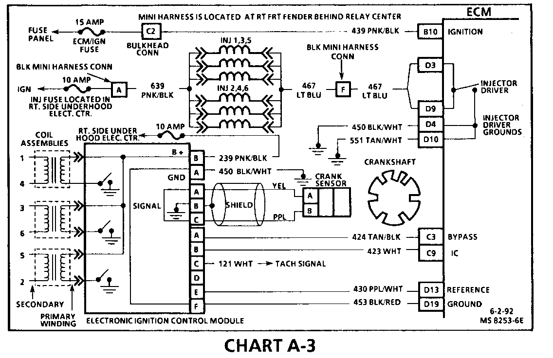
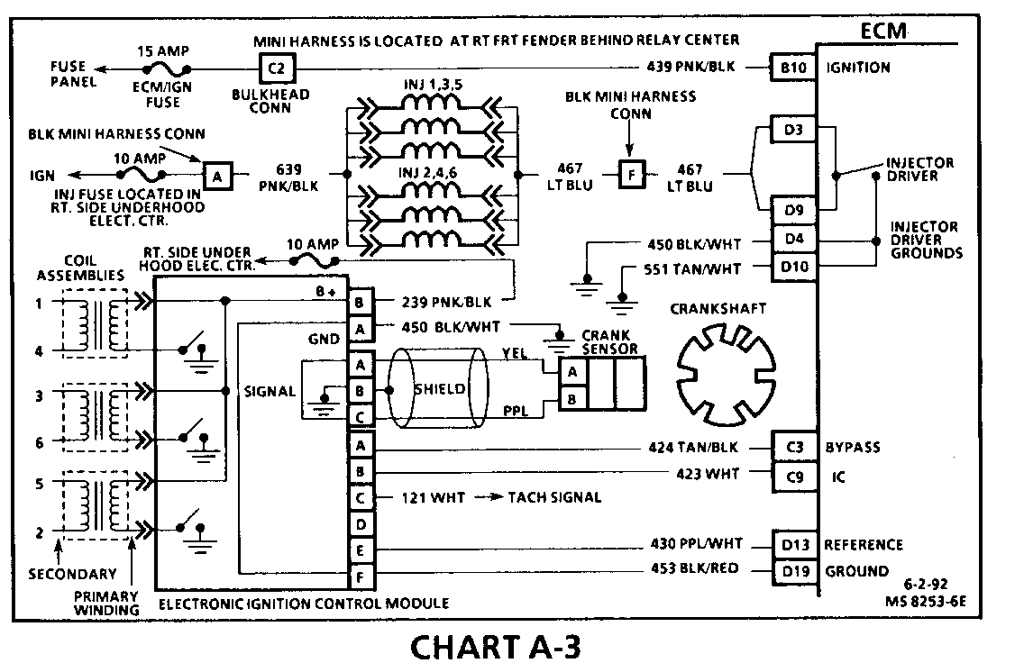
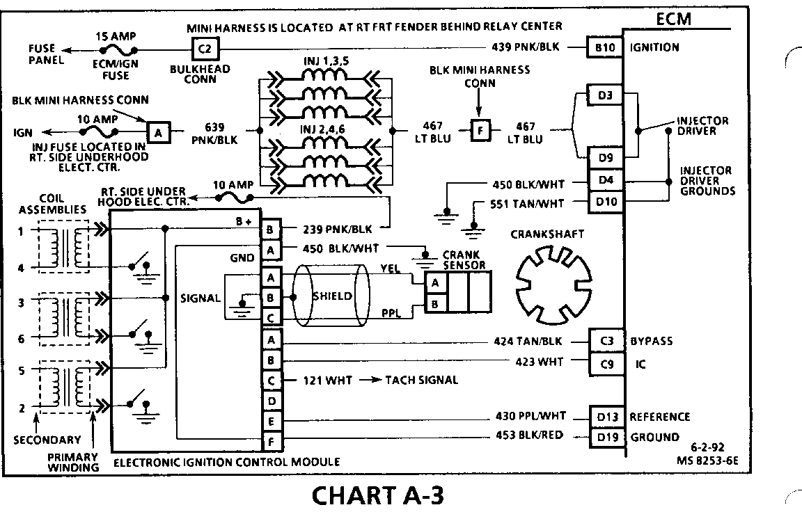
CHART A-3
ENGINE CRANKS BUT WILL NOT RUN 3.1L (VIN T) 3.4L(LQ1) "W" CARLINE (MFI) ---------------------------------------------------------------------- Circuit Description: ------------------- This chart assumes that battery condition and engine cranking speed are OK, and there is adequate fuel in the tank.
Test Description: Number(s) below refer to circled number(s) on the diagnostic chart.
1. A MIL (Service Engine Soon) "ON" is a basic test to determine if there is a 12 volts supply and ignition 12 volts to ECM. No DLC may be due to an ECM problem and CHART A-2 will diagnose the ECM. If TP sensor is over 2.5 volts, the engine may be in the clear flood mode which will cause starting problems. The engine will not start without reference pulses and therefore the Tech 1 scan tool should read rpm (reference) during crank.
2. For the first two seconds with ignition "ON," or whenever reference pulses are being received, PPSW should indicate fuel pump circuit voltage (8 to 12 volts).
3. Because the direct ignition system uses two plugs and wires to complete the circuit of each coil, the opposite spark should be left connected. If RPM was indicated during crank, the ignition control module is receiving a crank signal, but no spark at this test indicates the ignition control module is not triggering the coils.
4. This test will determine if there is B + at the injectors. The injectors are powered by a 10 amp fuse located in the right side underhood electrical center.
5. This test will check the integrity, of the ECM injector driver.
6. This test will determine if CKT 467 is open between the mini harness connector and the injectors.
7. This test will determine if the ignition control module is not triggering the problem coil or if the tested coil is at fault. This test could also be performed by using another known good coil.
8. This test will determine if the ignition control module is not generating the reference pulse or if the wiring or ECM are at fault. By touching and removing a test light to 12 volts on CKT 430, a reference pulse should be generated. If RPM is indicated, the ECM and wiring are OK.
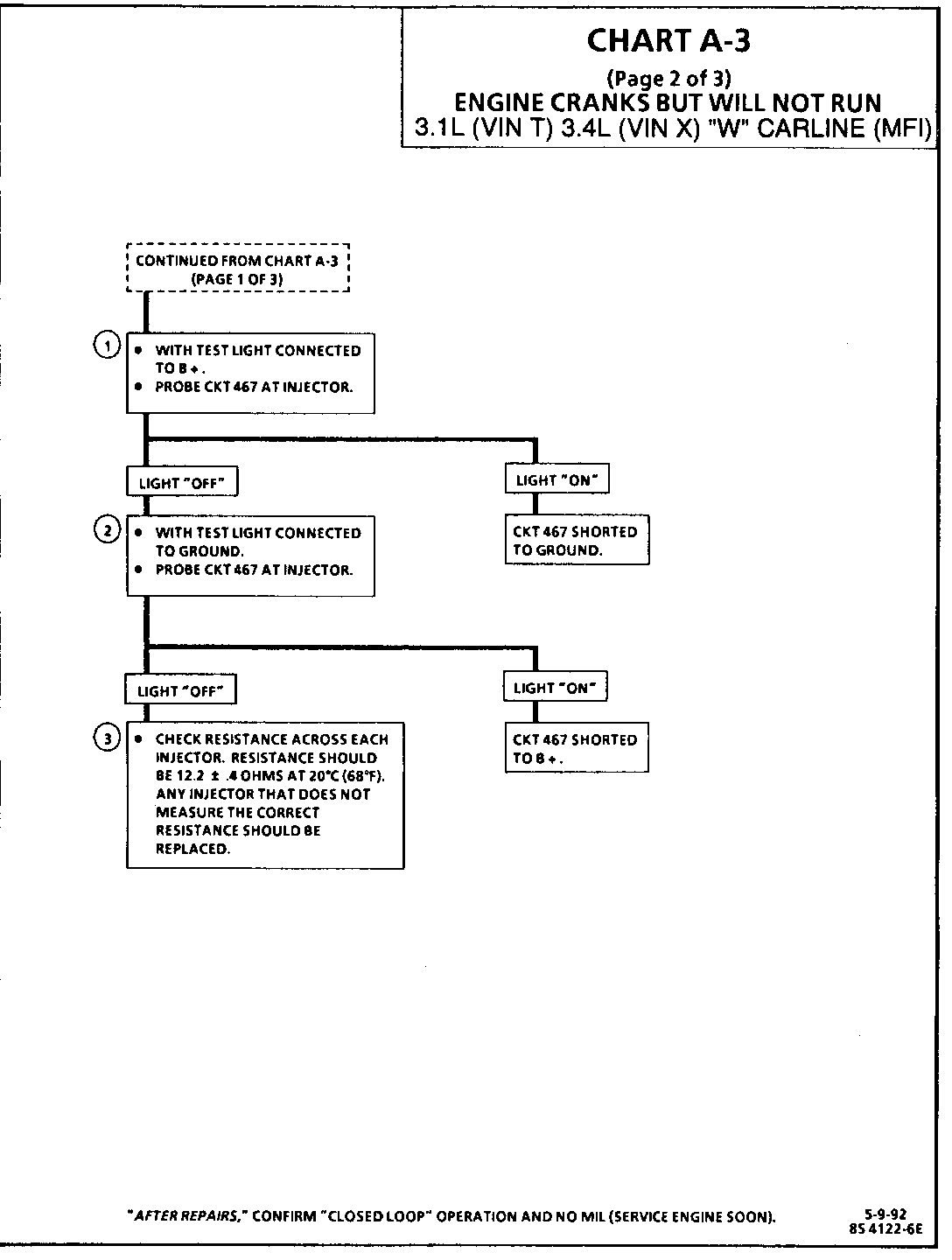
CHART A-3
ENGINE CRANKS BUT WILL NOT RUN 3.1L (VIN T) 3.4L(LQ1) "W" CARLINE (MFI) ---------------------------------------------------------------------- Test Description: Number(s) below refer to circled number(s) on the diagnostic chart.
1. This test will determine if CKT 467 is shorted to ground.
2. This test will determine if CKT 467 is shorted to B +.
3. Each individual injector resistance should be 12.2 +/- .4 ohms at 20 degrees Celsius (68 degrees Fahrenheit). Resistance will increase as temperature increases. An injector that does not meet specifications could cause the injector driver in the ECM to close and this would cause a cranks but no start situation.
CHART A-3
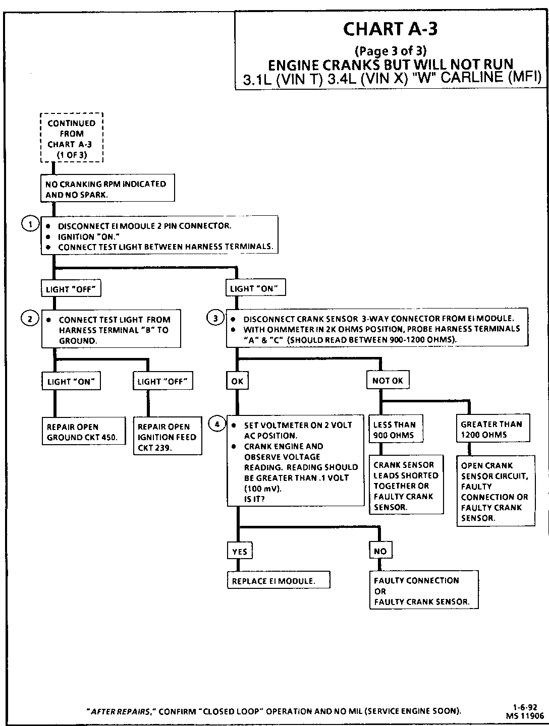
ENGINE CRANKS BUT WILL NOT RUN 3.1L (VIN T) 3.4L(LQ1) "W- CARLINE (MFI) ---------------------------------------------------------------------- Circuit Description: ------------------- If the Tech 1 "scan tool did not indicate a cranking RPM and there is no spark present at the plugs, the problem lies in the electronic ignition system or the power and ground supplies to the module.
The magnetic crank sensor is used to determine engine crankshaft position much the same way as the pick-up coil did in distributor type systems. The sensor is mounted in the block near a seven slot wheel on the crank shaft. The rotation of the wheel creates a flux change in the sensor which produces a voltage signal. The electronic ignition module then processes this signal and creates the reference pulses needed by the ECM and the signal triggers the correct coil at the correct time.
Test Description: Number(s) below refer to circled number(s) on the diagnostic chart.
1. This test will determine if the 12 volts supply and a good ground is available at the electronic ignition module.
2. Tests integrity of CKT 239 to the electronic ignition module. If test light does not light but the MIL is "ON" with ignition "ON," repair open in CKT 239.
3. Checks for continuity of the crank sensor and connections.
4. Voltage will vary in this test depending on cranking speed of engine.
General Motors bulletins are intended for use by professional technicians, not a "do-it-yourselfer". They are written to inform those technicians of conditions that may occur on some vehicles, or to provide information that could assist in the proper service of a vehicle. Properly trained technicians have the equipment, tools, safety instructions and know-how to do a job properly and safely. If a condition is described, do not assume that the bulletin applies to your vehicle, or that your vehicle will have that condition. See a General Motors dealer servicing your brand of General Motors vehicle for information on whether your vehicle may benefit from the information.
