Removal Procedure
Caution: Gasoline or gasoline vapors are highly flammable. A fire could occur if an ignition source is present. Never drain or store gasoline or diesel fuel in an open container, due to the possibility of fire or explosion. Have a dry chemical (Class B) fire extinguisher nearby.
Caution: Provide proper ventilation when working with fuel in enclosed areas where fuel vapors can collect. The lack of adequate ventilation may result in personal injury.
Caution: Always wear safety goggles when working with fuel in order to protect the eyes from fuel splash.
Important: Always replace the fuel sender O-rings when reinstalling the fuel sender assembly.
Important: Important the modular fuel sender assembly will spring-up when the snap ring is removed.
Important: Important when removing the modular fuel sender assembly from the fuel tank, the reservoir bucket on the fuel sender assembly is full of fuel. The modular fuel sender assembly must be tipped slightly during removal in order to avoid damage to the float. Place any remaining fuel into an approved container once the modular fuel sender assembly is removed from the fuel tank.
- Relieve the fuel system fuel pressure. Refer to Fuel Pressure Relief .
- Disconnect the negative battery cable.
- Drain the fuel tank to no more than 1/4 of a tank full. Refer to Fuel Tank Draining .
- Remove the spare tire cover, the jack, and the spare tire.
- Remove the trunk liner. Refer to Body Rear End.
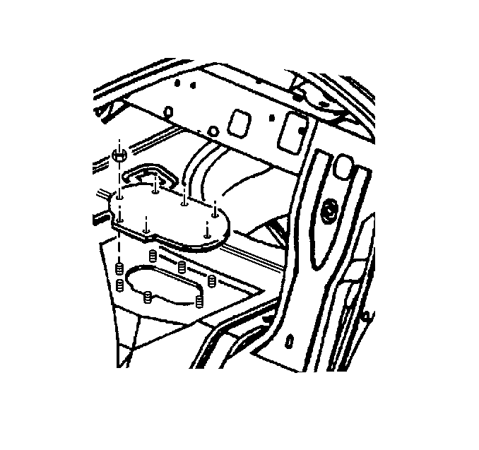
- Remove the (7) nuts retaining the fuel sender access panel.
- Remove the fuel sender access panel.
- Remove the fuel sender electrical connector.
- Clean the fuel pipes, and fuel sender assembly to prevent possible fuel contamination during removal.
- Remove the quick-connect fittings at the fuel sender assembly. Refer to Servicing Quick Connect Fittings .
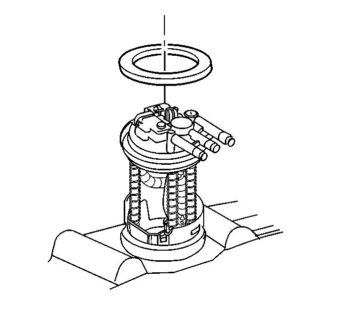
- Remove the fuel sender retaining snap ring.
- Remove the modular fuel sender assembly.
- Clean the fuel sender assembly O-ring sealing surfaces.
- Inspect the fuel sender assembly O-ring sealing surfaces.


Installation Procedure
Notice: Use the correct fastener in the correct location. Replacement fasteners must be the correct part number for that application. Fasteners requiring replacement or fasteners requiring the use of thread locking compound or sealant are identified in the service procedure. Do not use paints, lubricants, or corrosion inhibitors on fasteners or fastener joint surfaces unless specified. These coatings affect fastener torque and joint clamping force and may damage the fastener. Use the correct tightening sequence and specifications when installing fasteners in order to avoid damage to parts and systems.
Important: Care should be taken not to fold over or twist the fuel pump strainer when installing the fuel sender assembly, as this will restrict fuel flow. Also, assure that the fuel pump strainer does not block full travel of float arm.
Important: Important be sure that the fuel sender assembly retaining snap ring is fully seated within the tab slots on the fuel tank.
- Position the new fuel sender assembly O-ring on the fuel tank.
- Install the fuel sender assembly into the fuel tank.
- Install the fuel sender assembly retaining snap ring.
- Install the fuel sender electrical connector.
- Install the quick-connect fittings at the fuel sender assembly. Refer to Servicing Quick Connect Fittings .
- Install the negative battery cable.
- Install the fuel filler cap.
- Inspect for leaks.
- Install the fuel sender access panel.
- Install the (7) nuts retaining the fuel sender access panel.
- Install the trunk liner. Refer to Body Rear End.
- Install the spare tire, the jack, and the spare tire cover.

| 8.1. | Turn the ignition switch to the ON position for 2 seconds. |
| 8.2. | Turn the ignition switch to the OFF for 10 seconds. |
| 8.3. | Turn the ignition switch to the ON position again. |
| 8.4. | Check for fuel leaks. |

Tighten
Tighten the fuel sender access panel nuts to 10 N·m (8 lb ft)
Notice: Use the correct fastener in the correct location. Replacement fasteners must be the correct part number for that application. Fasteners requiring replacement or fasteners requiring the use of thread locking compound or sealant are identified in the service procedure. Do not use paints, lubricants, or corrosion inhibitors on fasteners or fastener joint surfaces unless specified. These coatings affect fastener torque and joint clamping force and may damage the fastener. Use the correct tightening sequence and specifications when installing fasteners in order to avoid damage to parts and systems.
