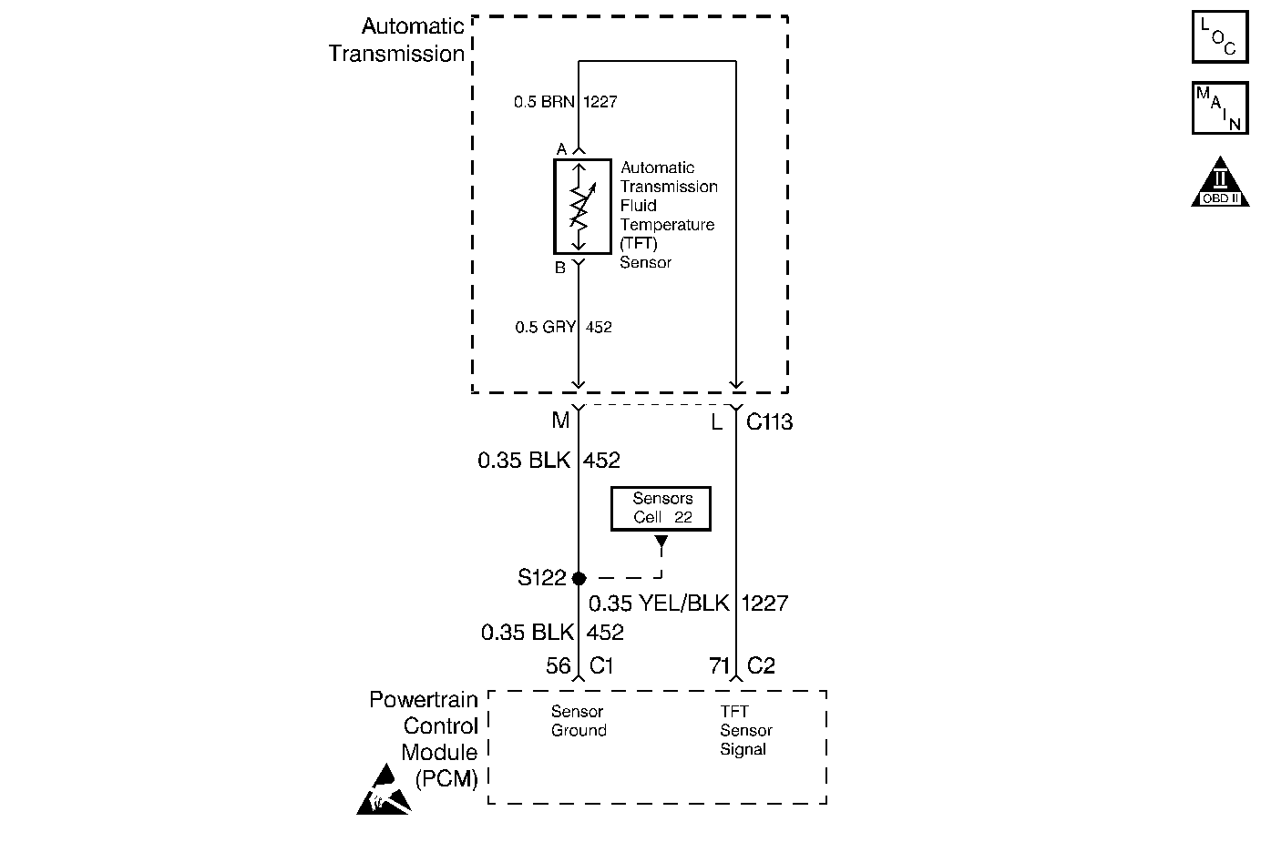
Circuit Description
The Automatic Transmission Fluid Temperature (TFT) sensor is a negative coefficient thermistor whose resistance value changes based on temperature. The PCM provides a 5 volt reference to the sensor on circuit 1227. A high fluid temperature or a short to ground on circuit 1227 results in low signal voltage. The TFT operating range is -40 to +151°C (-40 to +304°F).
If the PCM detects a continuous short to ground in the TFT sensor circuit, then DTC P0712 sets. DTC P0712 is a type D DTC.
Conditions for Setting the DTC
| • | The system voltage is 10-16 volts. |
| • | The ignition is ON. |
| • | The PCM detects a TFT sensor voltage of 0.200 volts or less for 10 seconds. |
Action Taken When the DTC Sets
| • | The PCM does not turn on the Malfunction Indicator Lamp (MIL). |
| • | The PCM disables shift adapts. |
| • | If the Engine Run Time is less than 3 minutes and: |
| - | Intake Air Temperature (IAT) DTC P0112, P0113, P1111, or P1112 is set, then the default TFT is 0°C (32°F). |
| - | No IAT DTC is set, then the default TFT is set to the IAT saved at start up. |
| • | If the engine run time is greater than 3 minutes, and the Engine Coolant Temperature (ECT) DTC P0117, P0118, P1114, or P1115 is set, then the default TFT is 131°C (268°F). |
| • | If the engine run time is greater than 3 minutes, no ECT DTC is set, and: |
| - | The ECT is less than 45°C (113°F), then the default TFT is 12°C (54°F). |
| - | The ECT is greater than 115°C (239°F), then the default TFT is 131°C (268°F). |
| - | The ECT is 45-115°C (113-239°F) and: |
| • | The IAT DTC P0112, P0113, P1111, or P1112 is set, then the default TFT is set to equal the ECT. |
| • | The IAT at start up is less than 0°C (32°F), then the default TFT is set to ECT minus 10°C (18°F). |
| • | The IAT at start up is greater than 28°C (82°F), then the default TFT is set to ECT plus 10°C (18°F). |
| • | The IAT at start up is 0-28°C (32-82°F), then the default TFT is set to equal ECT. |
Conditions for Clearing the DTC
| • | A scan tool can clear the DTC from the PCM history. The PCM clears the DTC from the PCM history if the vehicle completes 40 warm-up cycles without a failure reported. |
| • | The PCM cancels the DTC default actions when the fault no longer exists and the ignition is OFF long enough in order to power down the PCM. |
Diagnostic Aids
| • | Inspect the wiring for poor electrical connections at the PCM. Inspect the wiring for poor electrical connections at the transmission 20-way connector. Inspect the wiring for poor electrical connections at the Automatic Transmission Fluid Temperature sensor connector. Look for the following problems: |
| - | A bent terminal |
| - | A backed out terminal |
| - | A damaged terminal |
| - | Poor terminal tension |
| - | A chafed wire |
| • | When diagnosing for an intermittent short to ground or short to power, massage the wiring harness while watching the test equipment for a change. |
| • | Test the TFT sensor at various temperature levels to evaluate the possibility of a skewed (mis-scaled) sensor. Refer to Temperature vs Resistance . |
Test Description
The numbers below refer to the step numbers on the diagnostic table.
-
This step verifies DTC P0712 by indicating a short to ground. If the scan tool does not display a voltage value equal to or less than 0.200 volts, then the DTC is intermittent.
-
This step isolates the transmission. If the scan tool displays a voltage greater than 4.920 volts, then the Engine Wiring Harness is good.
Step | Action | Value(s) | Yes | No |
|---|---|---|---|---|
1 | Was the Powertrain On-Board Diagnostic (OBD) System Check performed? | -- | Go to A Powertrain On Board Diagnostic (OBD) System Check | |
2 | Has the transmission fluid checking procedure been performed? | -- | Go to Transmission Fluid Checking Procedure | |
Important: Before clearing the DTCs, use the scan tool in order to record the Failure Records for reference. The Clear Info function will erase the data. Does the scan tool display a TFT sensor voltage less than the specified value? | 0.200 volts | Go to Diagnostic Aids | ||
Does the scan tool display an Automatic Transmission Fluid Temperature voltage greater than the specified value? | 4.920 volts | |||
5 | Inspect circuit 1227 of the Engine Wiring Harness for a short to ground. Refer to Troubleshooting Procedures, Section 8. Did you find and correct the condition? | -- | ||
6 |
Does the J 39200 Digital Multimeter display a resistance greater than the specified value? | 100 ohms | ||
7 | Inspect circuit 1227 for a short to ground. Refer to Troubleshooting Procedures, Section 8. Did you find and correct the condition? | -- | ||
8 | Replace the Automatic Transmission Fluid Temperature sensor. Refer to TFT Sensor Replacement. Is the replacement complete? | -- | -- | |
9 | Replace the PCM. Refer to PCM Replacement/Programming Section 6. Is the replacement complete? | -- | -- | |
10 | In order to verify your repair, perform the following procedure:
Has the test run and passed? | -- | System OK |
