Battery Electrical Drain/Parasitic Load Test for Buick Regal 1998
Tools Required
J 38758 Parasitic Draw Test Switch Tool
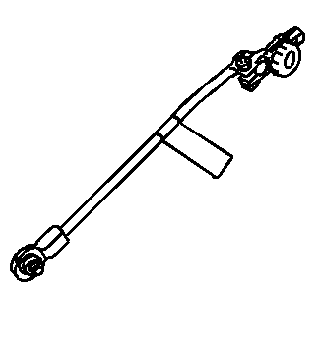
Notice: Do not turn the parasitic draw test switch to the OFF position with the engine running. Damage will occur to the vehicle's electrical system.
Notice: The test switch must be in the ON position when removing the fuses in order to maintain continuity in the electrical system. This avoids damaging the digital multimeter due to accidental overloading, such as a door being opened to change a fuse.
Important: The switch knob on the J 38758 is marked ON and OFF. When the switch knob is in the ON position, the circuit is closed and electrical current will pass through the switch. When the switch knob is in the OFF position, the circuit is open and electrical current will not pass through the switch.
- Disconnect the battery (ground) negative cable from the battery negative terminal. Refer to Battery Negative Cable Disconnection and Connection .
- Install the male end of the J 38758 to the battery ground (negative) terminal.
- Turn the J 38758 knob to the OFF position.
- Install the battery (ground) negative cable to the female end of the J 38758 .
- Turn the J 38758 knob to the ON position.
- Road test the vehicle and activate all of the accessories, including the radio and the air conditioning.
- Park the vehicle. Turn the ignition switch to the OFF position and remove the ignition switch key.
- Set a digital multimeter to the 10 A scale.
- Connect the digital multimeter to the test switch tool terminals.
- Turn the J 38758 knob to the OFF position. The current to flows through the digital multimeter.
- Wait one minute. Check and record the current reading.
- Turn the J 38758 knob to the OFF position. Wait 10 minutes.
- Check and record the current reading.
- Note the battery reserve capacity. Refer to Battery Usage .
- Check the charging system if the vehicle has an acceptable amount of current drain and the vehicle battery was weak or failed a load test. Refer to Charging System Check or Battery Is Undercharged or Overcharged .
- When the vehicle has an unacceptable amount of parasitic current drain, remove each fuse one at a time until the current drain falls to an acceptable level. This will indicate which circuit is causing the drain. Refer to Fuse Block Schematics in Wiring Systems to diagnose exactly which part of the suspect circuit is causing the parasitic drain. In some cases a non-fused circuit or component, such as a generator, is the cause of excessive parasitic current drain.
- Repeat the parasitic current drain test procedure after any repair has been completed to make sure that the parasitic current drain is at an acceptable level.
- When the cause of the excessive current draw has been located and repaired, remove the J 38758 .
- Connect the battery (ground) negative cable to the battery negative terminal. Refer to Battery Negative Cable Disconnection and Connection .
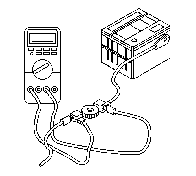
| • | When there is a current reading of 2 A or less, turn the J 38758 knob to the ON position. Continuity is maintained in the electrical system. |
| • | Then, switch the digital multimeter down to the 2 A scale for a more accurate reading when the J 38758 knob is turned OFF. |
| • | Divide the reserve capacity by 4. |
| • | Compare this to the multimeter milliampere reading taken in step 13. |
| • | The parasitic current drain should not exceed this number. |
| • | Example: If a battery has a reserve capacity of 100 minutes, the current drain should not exceed 25 milliamperes. |
Notice: The test switch must be in the ON position when removing the fuses in order to maintain continuity in the electrical system. This avoids damaging the digital multimeter due to accidental overloading, such as a door being opened to change a fuse.
Important: Opening doors and lifting door handles wakes up the BCM and a 10 minute time-out will start again when the door is closed or the door handle is released.
Component | Current Draw (mA) | Notes | |
|---|---|---|---|
Typical | Maximum | ||
BCM | 2.81 | 3.300 | -- |
DRL Module | .06 | 1.100 | -- |
ABS Module | 0.31 | 1.000 | -- |
RFA Module | 1.41 | 2.150 | -- |
PCM | .22 | 0.560 | -- |
Cluster | 0.0 | 1.000 | -- |
Generator | .17 | 2.000 | -- |
CJ2 HVAC Head | -- | 1.000 | 15 mA for 2.5 hours |
PWM Blower Control | -- | .500 | Only Max Spec Available |
Radio | 1.62 | 3.500 | SPEC - with theft LED active |
Cell Tel Amp | -- | .500 | Only Max Spec Available |
TOTAL | 6.600 | 16.870 | |
