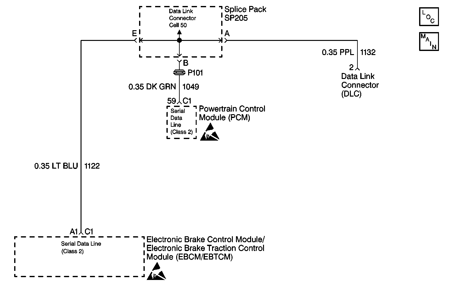
Circuit Description
The serial data communication circuit (CKT 1122, CKT 1132 and CKT 1049) transmits messages from one electronic control module to another when interface between systems is necessary. The ABS/ETS/TCS systems depend on information to and from the PCM for proper operation.
Conditions for Setting the DTC
DTC C1275 will set if either of the following conditions occurs:
| • | The vehicle speed is greater than 5 km/h (3 mph) and a malfunction exists on the serial data circuit. |
| • | The PCM has not broadcasted a serial message for at least 10 seconds. |
Action Taken When the DTC Sets
| • | A malfunction DTC stores. |
| • | The ETS/TCS disables. |
| • | The amber ETS/TCS warning indicator turns on. |
| • | The ABS remains functional. |
| • | No action towards the Electronic Brake Control Relay and ABS warning indicator is taken. |
Conditions for Clearing the DTC
| • | The condition responsible for setting the DTC no longer exists and the Scan Tool Clear DTCs function is used. |
| • | 100 drive cycles pass with no DTC(s) detected. |
Diagnostic Aids
When DTC 1275 is current (malfunction in CKT 1122, CKT 1132 or CKT 1049), no communication can be established with the scan tool. When the malfunction is removed, DTC C1275 will be stored in system memory.
The following conditions may cause an intermittent malfunction:
| • | A poor connection |
| • | Rubbed-through wire insulation |
| • | A broken wire inside the insulation |
Use the enhanced diagnostic function of the Scan Tool to measure the frequency of the malfunction. Refer to the Scan Tool manual for the procedure.
Thoroughly inspect any circuitry that may cause the intermittent complaint for the following conditions:
| • | Backed out terminals |
| • | Improper mating |
| • | Broken locks |
| • | Improperly formed or damaged terminals |
| • | Poor terminal-to-wiring connections |
| • | Physical damage to the wiring harness |
Important: Zero the J 39200 test leads before making any resistance measurements. Refer to the J 39200 user's manual.
Step | Action | Value(s) | Yes | No | ||||||
|---|---|---|---|---|---|---|---|---|---|---|
1 | Was the Diagnostic System Check performed? | -- | Go to Diagnostic System Check | |||||||
2 | Use the Scan Tool in order to establish communication with the same system on a different vehicle. Can communication be established on a different vehicle? | -- | ||||||||
3 |
Is there poor terminal contact, terminal corrosion, or terminal damage? | -- | ||||||||
4 |
Do not start the engine. Are DTC U1255, U1300 or U1301 set as a current DTC? | -- | Go to the appropriate DTC table | |||||||
5 | Was the Powertrain OBD System Check performed? Refer to Engine/Engine Controls Table of Contents. | |||||||||
6 |
Do not start the engine. Can communication be established with the Powertrain Control Module (PCM)? | -- | ||||||||
7 | Replace all the terminals or connectors that exhibit the following conditions:
Is the repair complete? | -- | Go to Diagnostic System Check | -- | ||||||
8 | Replace the EBCM/EBTCM. Is the repair complete? | -- | Go to Diagnostic System Check | -- | ||||||
9 | The malfunction is intermittent or is not present at this time. Refer to Diagnostic Aids for more information. | -- | -- | -- | ||||||
10 | The Scan Tool may be malfunctioning. Refer to the Scan Tool manual. Is the diagnosis complete? | -- | Go to Diagnostic System Check | -- |
