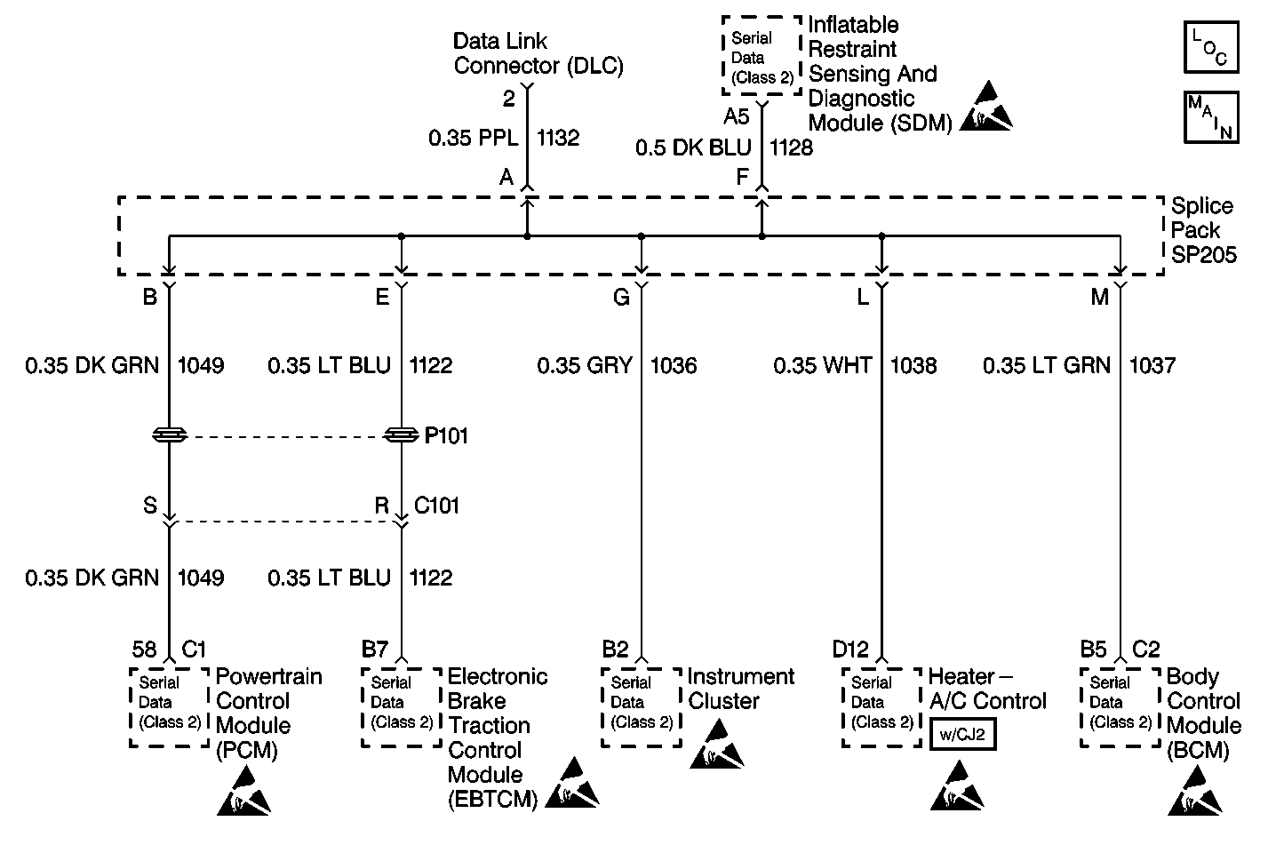
Circuit Description
Class 2 control modules receive a state of health message from the Electronic Brake Traction Control Module (EBTCM) through the Class 2 serial data link.
Conditions for Setting the DTC
Class 2 control modules do not receive a state of health message from the EBTCM.
Action Taken When the DTC Sets
| • | Class 2 control modules store DTC U1040 in memory. |
| • | The ABS indicator lamp turns on while the fault is present. |
Conditions for Clearing the DTC
| • | DTC U1040 will clear as a current DTC U1040 and will set as a history DTC U1040 when the class 2 control modules detect a state of health message from the EBTCM. |
| • | Using a scan tool. |
Diagnostic Aids
| • | The following conditions may cause an intermittent malfunction to occur: |
| • | An intermittent open or short to ground in circuit 1122. |
| • | Poor connections at the EBTCM. |
| • | An intermittent open in the Splice Pack SP205. |
| • | The Body Control Module (BCM) may store DTC U1040 if certain diagnostics are performed between the EBTCM and the Data Link Connector (DLC). |
| • | DTC P1626 will set in the Powertrain Control Module (PCM) when the ignition switch is on with the Body Control Module (BCM) disconnected. When BCM diagnostics and repairs are completed, refer to Engine Controls for additional information on PCM related DTCs. |
Test Description
The numbers below refer to the step numbers on the diagnostic table.
-
This step tests for an open in the Splice Pack SP205.
-
This step tests for a short to ground in circuit 1122.
-
This step tests for a short to B+ in circuit 1122.
-
This step tests for an open in circuit 1122.
Step | Action | Value(s) | Yes | No | ||||
|---|---|---|---|---|---|---|---|---|
Caution: Unless directed otherwise, the ignition and start switch must be in the OFF or LOCK position, and all electrical loads must be OFF before servicing any electrical component. Disconnect the negative battery cable to prevent an electrical spark should a tool or equipment come in contact with an exposed electrical terminal. Failure to follow these precautions may result in personal injury and/or damage to the vehicle or its components. Is the resistance measured less than the specified value? | 2ohms | |||||||
Is the resistance measured same as the specified value? | ∞ | |||||||
Is the voltage measured less than the specified value? | 2 V | |||||||
Is the resistance measured less than the specified value? | 5ohms | |||||||
5 |
Does the scan tool communicate with the EBTCM? | -- | ||||||
6 | Replace the Splice Pack SP205. Is the repair complete? | -- | -- | |||||
7 | Repair short to ground in circuit 1122. Is the repair complete? | -- | -- | |||||
8 | Repair short to B+ in circuit 1122. Is the repair complete? | -- | -- | |||||
9 | Repair poor connection or open in circuit 1122. Is the repair complete? | -- | -- | |||||
10 |
Is the action complete? | -- | -- | |||||
11 |
Is the action complete? | -- | System OK | -- |
