GM Service Manual Online
For 1990-2009 cars only

Purpose

The Electronic Ignition System controls fuel combustion by providing a spark to ignite the compressed air/fuel mixture at the correct time. To provide optimum engine performance, fuel economy, and control of exhaust emissions, the PCM controls the spark advance of the Ignition System. Electronic ignition has the following advantages over a Mechanical Distributor System:

    • No moving parts
    • Less maintenance
    • Remote mounting capability
    • No mechanical load on the engine
    • More coil cool down time between firing events
    • Elimination of mechanical timing adjustments
    • Increased available ignition coil saturation time

Operation

The Electronic Ignition System does not use the conventional distributor and coil. The Ignition System consists of three ignition coils, an ignition control module, a dual hall-effect crankshaft position sensor, an engine crankshaft balancer with interrupter rings attached to the rear, related connecting wires, and the ignition control (IC) and fuel metering portion of the PCM.

Conventional ignition coils have one end of the secondary winding connected to the engine ground. In this Ignition System, neither end of the secondary winding is grounded. Instead, each end of a coils secondary winding is attached to a spark plug. Each cylinder is paired with the cylinder that is opposite it, 1/4, 2/5, 3/6. These two plugs are on companion cylinders, i.e., on top dead center at the same time. When the coil discharges, both plugs fire at the same time to complete the series circuit. The cylinder on compression is said to be the event cylinder and the one on exhaust is the waste cylinder. The cylinder on the exhaust stroke requires very little of the available energy to fire the spark plug. The remaining energy will be used as required by the cylinder on the compression stroke. The same process is repeated when the cylinders reverse roles. This method of ignition is called a Waste Spark Ignition System.

Since the polarity of the ignition coil primary and secondary windings is fixed, one spark plug always fires with normal polarity and its companion plug fires with reverse polarity. This differs from a conventional Ignition System that fires all the plugs with the same polarity. Because the ignition coil requires approximately 30 percent more voltage to fire a spark plug with reverse polarity, the ignition coil design is improved, with saturation time and primary current flow increased. This redesign of the system allows higher secondary voltage to be available from the ignition coils - more than 40 kilovolts (40,000 volts) at any engine RPM. The voltage required by each spark plug is determined by the polarity and the cylinder pressure. The cylinder on the compression stroke requires more voltage to fire the spark plug than the cylinder on the exhaust stroke.

It is possible for one spark plug to fire even though a plug wire from the same coil may be disconnected from its companion plug. The disconnected plug wire acts as one plate of a capacitor, with the engine being the other plate. These two capacitor plates are charged as a spark jumps across the gap of the connected spark plug. The plates are then discharged as the secondary energy is dissipated in an oscillating current across the gap of the spark plug that is still connected. Secondary voltage requirements are very high with an open spark plug or spark plug wire. The ignition coil has enough reserve energy to fire the plug that is still connected at idle, but the coil may not fire the spark plug under high engine load. A more noticeable misfire may be evident under load, both spark plugs may then be misfiring.

System Components


Object Number: 12303  Size: SH

Crankshaft Position Sensor and Crankshaft Balancer Interrupter Rings

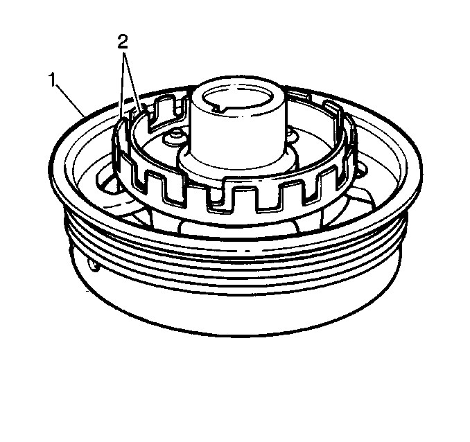
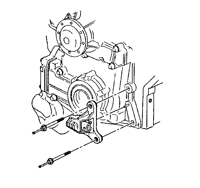
The dual crankshaft position sensor is secured in an aluminum mounting bracket and bolted to the front left side of the engine timing chain cover, partially behind the crankshaft balancer. A 4-wire harness connector plugs into the sensor, connecting it to the ignition control module. The dual crankshaft position sensor contains two hall-effect switches with one shared magnet mounted between them. The magnet and each hall-effect switch are separated by an air gap. A hall-effect switch reacts like a solid state switch, grounding a low current signal voltage when a magnetic field is present. When the magnetic field is shielded from the switch by a piece of steel placed in the air gap between the magnet and the switch, the signal voltage is not grounded. If the piece of steel, called an interrupter, is repeatedly moved in and out of the air gap, the signal voltage will appear to go ON - OFF - ON - OFF - ON - OFF. In the case of the Electronic Ignition System, the piece of steel is two concentric interrupter rings mounted to the rear of the crankshaft balancer.


Object Number: 12358  Size: SH
(1)Crankshaft Balancer
(2)Interrupter Rings

Each interrupter ring has blades and windows that either block the magnetic field or allow it to close one of the hall-effect switches. The outer hall-effect switch produces a signal called the CKP 18X because the outer interrupter ring has 18 evenly spaced blades and windows. The CKP 18X portion of the crankshaft position sensor produces 18 ON - OFF pulses per crankshaft revolution. The hall-effect switch closest to the crankshaft, the CKP sync portion of the sensor, produces a signal that approximates the inside interrupter ring. The inside interrupter ring has 3 unevenly spaced blades and windows of different widths. The CKP sync portion of the crankshaft position sensor produces 3 different length ON - OFF pulses per crankshaft revolution. When a CKP sync interrupter ring window is between the magnet and inner switch, the magnetic field will cause the CKP sync hall-effect switch to ground the CKP sync signal voltage supplied from the ignition control module. The CKP 18X interrupter ring and hall-effect switch react similarly. The ignition control module interprets the CKP 18X and CKP sync ON - OFF signals as an indication of crankshaft position, and the ignition control module must have both signals to fire the correct ignition coil. The ignition control module determines crankshaft position for correct ignition coil sequencing by counting how many CKP 18X signal transitions occur, i.e.; ON - OFF or OFF - ON, during a CKP sync pulse.


Object Number: 12305  Size: SH

Camshaft Position (CMP) Sensor

The camshaft position sensor is located on the timing cover behind the water pump near the camshaft sprocket. As the camshaft sprocket turns, a magnet in it activates the hall-effect switch in the camshaft position sensor. When the hall-effect switch is activated, it grounds the signal line to the ICM, pulling the camshaft position sensor signal circuits applied voltage low. This is interpreted as a CMP sensor signal. The CMP sensor signal is created as piston #1 is approximately 25 degrees after top dead center on the power stroke.
Ignition Control Module and Ignition Coil


Object Number: 12299  Size: SH
(1)Screws
(2)Ignition Coil
(3)Ignition Control Module

Ignition Coils

Three twin-tower ignition coils are individually mounted to the ignition control module. Each coil provides spark for two plugs simultaneously, waste spark distribution. Each coil is serviced separately. Two terminals connect each coil pack to the module. Each coil is provided a fused ignition feed. The other terminal at each coil is individually connected to the module, which will energize one coil at a time by completing and interrupting the primary circuit ground path to each coil at the proper time.

Ignition Control Module (ICM)

The ignition control module performs the following functions:

    • It powers the dual crankshaft position sensor internal circuits.
    • It supplies the voltage signals that each respective hall-effect switch pulses to ground to generate the CKP sync and CKP 18X signal pulses.
    • It determines the correct ignition coil firing sequence, based on how many CKP 18X signal transitions occur during a CKP sync pulse. This coil sequencing occurs at start-up. After the engine is running, the module remembers the sequence, and continues triggering the ignition coils in proper sequence.
    • It determines whether or not the crankshaft is rotating in the proper direction, and cuts off fuel delivery and spark to prevent backfiring if reverse rotation is detected.
    • It sends the 3X reference and 18X reference signals to the PCM. The PCM determines engine RPM from these signal. These signals used by the PCM to determine crankshaft speed for ignition control (IC) spark advance calculations. The falling edge of each 3X reference and 18X reference signal pulse occurs at a specific time in relation to top dead center of any cylinder stroke. The 3X reference signal sent to the PCM by the ignition control module is an ON - OFF pulse occurring 3 times per crankshaft revolution. This is neither the CKP sync pulse nor the 18X crankshaft position sensor pulse, but both of these are required before the ignition control module will generate the 3X reference signal. The ignition control module generates the 3X reference signal by an internal divide-by-6 circuit. This divider circuit divides the CKP 18X signal pulses by 6. The divider circuit is enabled, or ready to begin dividing, only after it receives a crankshaft position sensor CKP sync pulse. After beginning, the divider circuit does not need the Sync pulses to continue operating. If either the CKP 18X or CKP sync pulses are missing at start-up, the ignition control module will not generate 3X reference or 18X reference signal pulses and no fuel injector pulses will occur.

Powertrain Control Module (PCM)


Object Number: 159242  Size: SH

The PCM is responsible for maintaining proper spark and fuel injection timing for all driving conditions. Ignition control (IC) spark timing is the PCMs method of controlling spark advance and ignition dwell. To provide optimum driveability and emissions, the PCM monitors input signals from the following components in calculating ignition control (IC) spark timing:

    • Ignition control module (ICM)
    • Engine coolant temperature (ECT) sensor
    • Intake air temperature (IAT) sensor
    • Mass air flow (MAF) sensor
    • Internal Mode or PNP inputs from Internal Mode switch or Park/Neutral position switch
    • Throttle position (TP) sensor
    • Vehicle speed sensor (VSS)/trans output speed sensor (TOSS)

The Ignition System uses many of the same ignition module-to-PCM circuits as did previous Delco Engine Management Systems using distributor type ignition. The following describes the PCM to ignition control module circuits:

    • 3X reference PCM input -- From the ignition control module, the PCM uses this signal to calculate engine RPM and crankshaft position. The PCM compares pulses on this circuit to any that are on the Reference Low circuit, ignoring any pulses that appear on both. The PCM also uses the pulses on this circuit to initiate injector pulses.
    • 18X reference PCM input -- The 18X reference signal is used to accurately control spark timing at low RPM and allow IC operation during crank. Below 1200 RPM, the PCM is monitoring the 18X reference signal and using it as the reference for ignition timing advance. When engine speed exceeds 1200 RPM, the PCM begins using the 3X reference signal to control spark timing.
    • Camshaft position PCM input -- The PCM uses this signal to determine the position of the cylinder #1 piston during its power stroke. This signal is used by the PCM to calculate true Sequential Fuel Injection (SFI) Mode of operation. The PCM compares the number of CAM pulses to the number of 18X and 3X reference pulses. If the number of 18X and 3X reference pulses occurring between CAM pulses is incorrect, or if no CAM pulses are received while the engine is running, the PCM will set DTC P0341. If the cam signal is lost while the engine is running the Fuel Injection System will shift to a calculated Sequential Fuel Injection Mode based on the last CAM pulse, and the engine will continue to run. The engine can be re-started and will run in the calculated Sequential Mode as long as the condition is present with a 1 in 6 chance of being correct.
    • Reference low PCM input -- This is a ground circuit for the digital RPM counter inside the PCM, but the wire is connected to engine ground only through the ignition control module. Although this circuit is electrically connected to the PCM, it is not connected to ground at the PCM. The PCM compares voltage pulses on the 3X or 18X reference input to those on this circuit, ignoring pulses that appear on both.
    • Bypass signal PCM output -- The ignition control module maintains a fixed spark timing while the engine is cranking, Bypass Mode. Once the PCM receives 3X reference pulses, the PCM commands the ignition module to allow the PCM to control the spark advance, IC Mode. The ignition control module determines the correct operating mode based on the voltage level that the PCM sends to the ignition control module on the bypass circuit. The PCM provides 5 volts on the bypass circuit if the PCM is going to control spark timing, IC Mode.
    • Ignition control (IC) PCM output -- The IC output circuitry of the PCM sends out timing pulses to the ignition control module on this circuit. When in the Bypass Mode, the ignition control module grounds these pulses. When in the IC Mode, these pulses are sent to the ignition control module to control coil dwell and spark timing. Proper sequencing of the 3 ignition coils, i.e.; which coil to fire, is always the job of the ignition control module.

Ignition System Modes of Operation

Anytime the PCM does not apply 5 volts to the ignition control module bypass circuit, the ignition control module controls ignition by triggering each of the three coils in the proper sequence at a pre-determined dwell. This is called Bypass Mode ignition.

When the PCM begins receiving 18X reference and 3X reference pulses, the PCM applies 5 volts to the ignition control module bypass circuit. This signals the ignition control module to allow the PCM to control the dwell and spark timing. This is IC Mode ignition. During IC Mode, the PCM compensates for all driving conditions.

In the IC Mode, the ignition spark timing and ignition dwell time is fully controlled by the PCM. The ignition control module is responsible for proper ignition coil sequencing during both Bypass Mode and IC Mode. IC spark advance and ignition dwell is calculated by the PCM using the following inputs:

    • Engine speed, 18X reference or 3X reference
    • Crankshaft position, 18X reference or 3X reference and camshaft position PCM input signal
    • Engine coolant temperature (ECT) sensor
    • Throttle position (TP) sensor
    • Knock signal, knock sensor
    • Park/Neutral position, Internal Mode switch or Park/Neutral position switch
    • Vehicle speed, vehicle speed sensor/trans output speed sensor
    • PCM and Ignition System supply voltage, PCM ignition feed voltage

Once the change is made to IC Mode, it will stay in effect until one of the following conditions occurs:

    • The engine is turned OFF.
    • The engine quits running.

If a PCM/IC fault DTC P1351, P1352, P1361 and P1362 is detected while the engine is running, the engine may quit running. However the vehicle will restart, and may remain in Bypass Mode with a noticeable loss of performance.

Diagnosis

If the 18X reference signal is not received by the PCM while the engine is running, a DTC P0336 will be set and 3X reference will be used to control spark advance under 1200 RPM, and Bypass Mode will be in effect under 400 RPM. The engine will continue to run and start normally.

If the 3X reference signal is not received by the PCM while the engine is running, the PCM will use the 18X reference pulses to calculate RPM and crankshaft position. The engine will continue to run and start normally, but DTC P1374 will be set.

Poor engine performance and possibly a MIL with no DTC can be caused if the Reference Low circuit is open or connected to ground at the PCM.

The IC output circuitry in the PCM generates IC output pulses anytime crankshaft reference signal input pulses are being received. When the ignition system is operating in the Bypass Mode, no voltage on the bypass control circuit, the ignition control module grounds the IC pulses coming from the PCM. The ignition control module will remove the ground from the IC circuit only after switching to the IC Mode. The PCM commands switching to IC Mode by applying 5 volts on the bypass circuit to the ignition control module. The PCM monitors the IC and Bypass circuits for electrical malfunctions affecting proper Ignition System operation. If a malfunction occurs, diagnosis is included in DTC P1351, P1352, P1361, and P1362 diagnostic tables. If diagnostic trouble codes are encountered, go to Diagnostic Trouble Code (DTC) List/Type for diagnosis.

The following information will list important considerations to aid the technician in servicing the Ignition System:

    • The ignition coils secondary voltage output capabilities are very high - more than 40,000 volts. Avoid body contact with ignition high voltage secondary components when the engine is running, or personal injury may result!
    • The dual hall-effect crankshaft position sensor is the most critical part of the Ignition System. If the sensor is damaged so that the CKP 18X or CKP sync crank sensor pulses are not generated, the engine will not start!
    • There are 4 circuit wires connecting the dual crankshaft position sensor to the ignition control module. If there is a problem with any of the four, the engine will not start, no spark and no injector pulses. The circuits are described as follows:
       - The 10 to 12 volt sensor feed for the hall-effect switches from the ignition control module.
       - The CKP 18X pulse signal to the ignition control module.
       - The CKP sync pulse signal to the ignition control module.
       - The sensor ground circuit for both hall-effect switches.
    • If the CKP sync pulses stop while the engine is running, the engine will keep running. However, it will not restart after being shut OFF.
    •  If the CKP 18X pulses stop while the engine is running, the engine will stop running and will not restart.
    • Crankshaft position sensor clearance is very important! The sensor must not contact the rotating interrupter rings at any time, or sensor damage will result. If the balancer interrupter rings are bent, the interrupter ring blades will destroy the sensor.
    • Ignition timing is not adjustable. There are no timing marks on the crankshaft balancer or timing chain cover.
    • If crankshaft position sensor replacement is necessary, the crankshaft balancer must be removed first. The balancer is a press fit onto the crankshaft. Removing the serpentine accessory drive belt and balancer attaching bolt will allow its removal with J 38197-A balancer remover.
    • When reinstalling, torque the balancer attachment bolt. This is critical to ensure the balancer stays attached to the crankshaft.
    • If a crankshaft position sensor assembly is replaced, check the crankshaft balancer interrupter rings for any blades being bent. If this is not checked closely and a bent blade exists, the new crankshaft position sensor can be destroyed by the bent blade with only one crankshaft revolution!
    • Neither side of the ignition coil primary or secondary windings is connected to engine ground. Although the ignition coil packs are secured to the ignition control module, it is not an electrical connection to ground.
    • Be careful not to damage the secondary ignition wires or boots when servicing the Ignition System. Rotate each boot to dislodge it from the plug or coil tower before pulling it from either a spark plug or the ignition coil. Never pierce a secondary ignition wire or boot for any purpose! Future problems are guaranteed if pinpoints or test lamps are pushed through the insulation for testing.
    • The ignition control module is grounded to the engine block through a ground wire to the ignition control module bracket mounting stud. If servicing is required, ensure that good electrical contact is made between the ground and the mounting bracket, including proper hardware and torque.
    • A conventional tachometer used to check RPM on a primary ignition tach lead will not work on this Ignition System. To check RPM, use either of the following items:
       - A tachometer designed with an inductive pickup, used on the secondary side of an Ignition System. These tachs are identified by a clamp that goes around a spark plug wire. Set the tach to 2-cycle operation. The 2-cycle setting is required because spark plugs on this engine fire every time the piston is at the top of its stroke. If a 2 cycle selection is not available, divide the indicated 4 cycle reading by 2.
       - A scan tool.