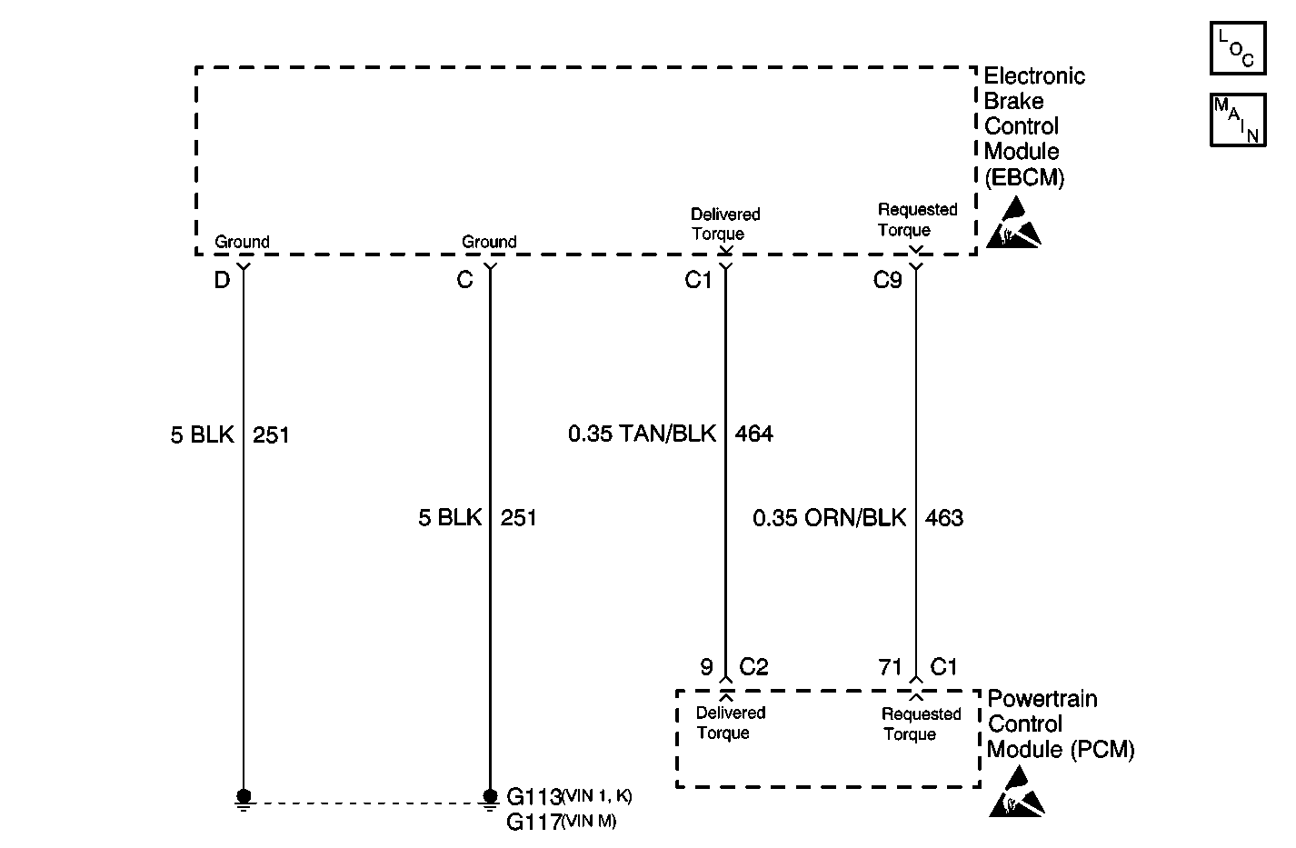
Circuit Description
Traction Control is simultaneously controlled by the EBCM and the Powertrain Control Module (PCM). The PCM receives a REQUESTED TORQUE request via a Pulse Width Modulated (PWM) signal from the EBCM requesting the desired torque level for proper Traction Control system operation. The PCM supplies the pull up voltage.
Conditions for Running the DTC
The ignition is ON.
Conditions for Setting the DTC
DTC C1277 can be set when there is an open or short in the Requested Torque line between the EBCM and PCM or there is a TCS communication malfunction detected by the PCM and indicated to the EBCM, by broadcasting a Class 2 message.
Action Taken When the DTC Sets
| • | TCS is disabled. |
| • | Traction Control (TRAC OFF) indicator is turned on. |
| • | Service Vehicle Soon Indicator is turned on. |
| • | ABS remains functional. |
Conditions for Clearing the DTC
Condition for DTC is no longer present and scan tool is used to clear the history DTC.
Diagnostic Aids
| • | Possible causes for DTC C1277 to set are: |
| - | Requested Torque line open. |
| - | Requested Torque line shorted to ground. |
| - | Requested Torque line shorted to voltage. |
| - | Communication frequency malfunction. |
| - | PCM not receiving Class 2 message. |
| • | It is very important that a thorough inspection of the wiring and connectors be performed. Failure to carefully and fully inspect wiring and connectors may result in misdiagnosis, causing part replacement with reappearance of the malfunction. |
| • | If an intermittent malfunction exists refer to Testing for Intermittent Conditions and Poor Connections in Wiring Systems. |
Step | Action | Value(s) | Yes | No | ||||||||
|---|---|---|---|---|---|---|---|---|---|---|---|---|
1 | Did you perform the ABS Diagnostic System Check? | -- | Go to Step 2 | |||||||||
2 |
Does the scan tool display DTC P1571 as current? | -- | Go to Step 3 | |||||||||
3 | Inspect the following grounds, making sure each ground is clean and torqued to the proper specification:
Refer to Wiring Repairs in Wiring Systems. Did you find and correct the condition? | -- | Go to Step 13 | Go to Step 4 | ||||||||
4 | With a scan tool, observe the Requested Torque parameter in the ABS/ETS/TCS data list. Does the scan tool display within the specified range? | 5-95% | Go to Step 5 | Go to Step 7 | ||||||||
5 |
Important: Removing battery voltage or ground from the EBCM will result in the
following conditions:
Important: Disconnecting the EBCM connector and turning ON the ignition could cause
other modules to set loss of communication DTCs (Uxxxx). Once the EBCM is
reconnected, the EBCM may set one or both of the following DTCs:
Does the percentage measure within the specified range? | 5-95% | Go to Step 6 | Go to Step 7 | ||||||||
6 | Measure the DC Hz between the requested torque signal circuit and ground. Does the frequency measure within the specified range? | 121-134 Hz | Go to Step 11 | Go to Step 10 | ||||||||
7 | Test the requested torque signal circuit for an open. Refer to Circuit Testing and Wiring Repairs in Wiring Systems. Did you find and correct the condition? | -- | Go to Step 13 | Go to Step 8 | ||||||||
8 | Test the requested torque signal circuit for a short to ground. Refer to Circuit Testing and Wiring Repairs in Wiring Systems. Did you find and correct the condition? | -- | Go to Step 13 | Go to Step 9 | ||||||||
9 | Test the requested torque signal circuit for a short to voltage. Refer to Circuit Testing and Wiring Repairs in Wiring Systems. Did you find and correct the condition? | -- | Go to Step 13 | Go to Step 10 | ||||||||
10 | Inspect the EBCM harness connector for poor connections/terminal tension. Refer to Testing for Intermittent Conditions and Poor Connections and Connector Repairs in Wiring Systems. Did you find and correct the condition? | -- | Go to Step 13 | Go to Step 12 | ||||||||
11 | Inspect the PCM. Refer to Powertrain On Board Diagnostic (OBD) System Check in Engine Controls. Did you find and correct the condition? | -- | Go to Step 13 | Go to Diagnostic Aids | ||||||||
12 | Replace the EBCM. Refer to Electronic Brake Control Module Replacement Did you complete the repair? | -- | Go to Step 13 | -- | ||||||||
13 |
Does the DTC reset? | -- | Go to Step 2 | System OK |
