HVAC Connector End Views CJ4
| Table 1: | A/C Compressor Clutch Coil |
| Table 2: | A/C Refrigerant Pressure Sensor |
| Table 3: | Blower Motor Control Module |
| Table 4: | Air Temperature Actuator-Front |
| Table 5: | Air Temperature Actuator-Rear |
| Table 6: | Front HVAC Control Assembly |
| Table 7: | Ambient Outside Air Temperature Sensor |
| Table 8: | Vacuum/Electric Solenoid |
| Table 9: | Rear HVAC Control Assembly |
| Table 10: | Rear Mode Actuator |
| Table 11: | Two Stage Orifice Relay |
| Table 12: | Two Stage Orifice Solenoid |
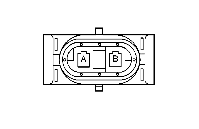
| |||||||
|---|---|---|---|---|---|---|---|
Connector Part Information |
| ||||||
Pin | Wire Color | Circuit No. | Function | ||||
A | BLK | 1050 | Ground | ||||
B | DK GRN | 59 | A/C Compressor Clutch Supply Voltage | ||||
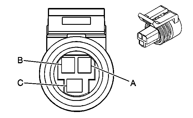
| |||||||
|---|---|---|---|---|---|---|---|
Connector Part Information |
| ||||||
Pin | Wire Color | Circuit No. | Function | ||||
A | BLK | 2751 | Low Reference | ||||
B | GRY | 474 | 5 Volt Reference | ||||
C | RED/BLK | 380 | A/C Refrigerant Pressure Sensor Signal | ||||
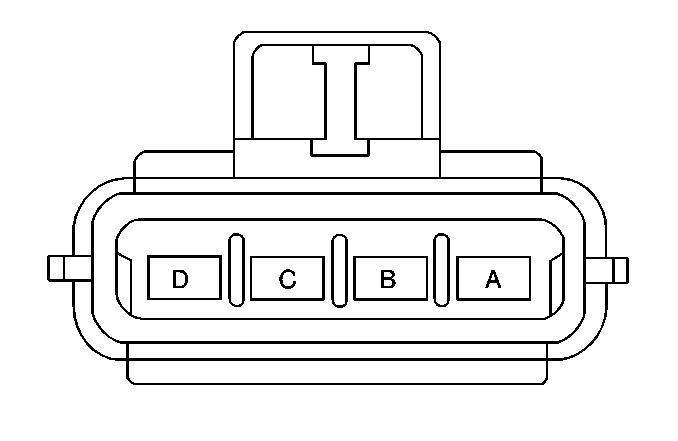
| |||||||
|---|---|---|---|---|---|---|---|
Connector Part Information |
| ||||||
Pin | Wire Color | Circuit No. | Function | ||||
A | BLK | 150 | Ground | ||||
B | ORN | 40 | Battery Positive Voltage | ||||
C | GRY/BLK | 754 | Blower Motor Speed Control | ||||
D | -- | -- | Not Used | ||||
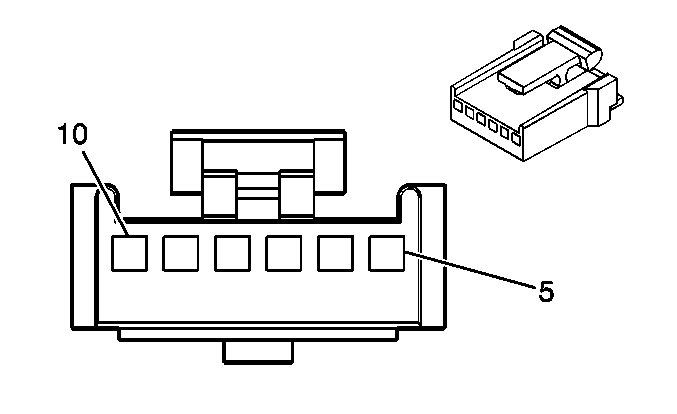
| |||||||
|---|---|---|---|---|---|---|---|
Connector Part Information |
| ||||||
Pin | Wire Color | Circuit No. | Function | ||||
5-6 | -- | -- | Not Used | ||||
7 | BLK | 1450 | Ground | ||||
8 | DK BLU | 2210 | Front Temperature Control Signal | ||||
9 | -- | -- | Not Used | ||||
10 | BRN | 41 | Ignition 3 Voltage | ||||

| |||||||
|---|---|---|---|---|---|---|---|
Connector Part Information |
| ||||||
Pin | Wire Color | Circuit No. | Function | ||||
5-6 | -- | -- | Not Used | ||||
7 | BLK | 1450 | Ground | ||||
8 | YEL | 2214 | Rear Control Assembly Temperature Selector Control Signal | ||||
9 | -- | -- | Not Used | ||||
10 | BRN | 41 | Ignition 3 Voltage | ||||
| |||||||
|---|---|---|---|---|---|---|---|
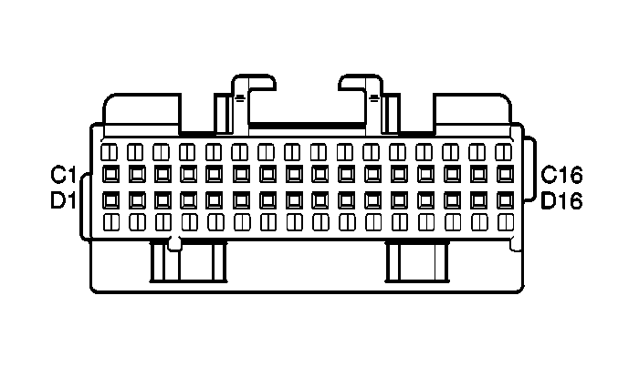
Connector Part Information |
| ||||||
Pin | Wire Color | Circuit No. | Function | ||||
C1-C4 | -- | -- | Not Used | ||||
C5 | BRN | 41 | Ignition 3 Voltage | ||||
C6 | -- | -- | Not Used | ||||
C7 | DK BLU | 2210 | Front Temperature Control Signal | ||||
C8 | -- | -- | Not Used | ||||
C9 | ORN | 2212 | Rear A/C Led Control | ||||
C10 | -- | -- | Not Used | ||||
C11 | GRY/BLK | 754 | Blower Speed Control Signal | ||||
C12 | ORN | 640 | Battery Positive Voltage | ||||
C13 | WHT | 2258 | Two Stage Orifice Solenoid Control | ||||
C15 | DK GRN | 2211 | Rear Fan Up/Down Request | ||||
C16 | GRY | 8 | Instrument Panel Lamp Supply Voltage-1 | ||||
D1 | YEL | 61 | Low Reference | ||||
D2 | -- | -- | Not Used | ||||
D3 | LT GRN/BLK | 735 | Ambient Air Temperature Sensor Signal | ||||
D4-D5 | -- | -- | Not Used | ||||
D6 | PNK | 2216 | Rear AC/RECIRC Request | ||||
D7 | DK BLU | 2213 | Rear RECIRC Led Control | ||||
D8 | TAN | 363 | Recirculation Mode Valve Solenoid Control | ||||
D9 | PPL | 361 | Mix-blend Mode Valve Solenoid Control | ||||
D10 | RED | 362 | Lower Mode Valve Solenoid Control | ||||
D11 | LT GRN/BLK | 366 | Defrost Mode Valve Solenoid Control | ||||
D12 | WHT | 1038 | HVAC Class 2 Serial Data | ||||
D13 | LT BLU | 706 | Upper Mode Valve Solenoid Control | ||||
D14 | -- | -- | Not Used | ||||
D15 | WHT | 193 | Rear Defog Relay Control | ||||
D16 | -- | -- | Not Used | ||||
| |||||||
|---|---|---|---|---|---|---|---|
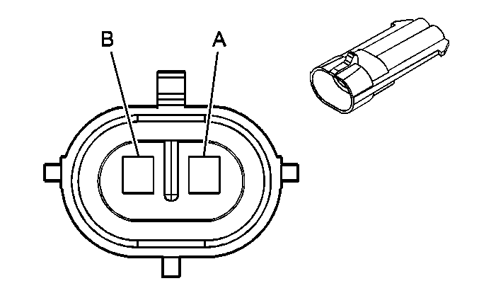
Connector Part Information |
| ||||||
Pin | Wire Color | Circuit No. | Function | ||||
A | LT GRN/BLK | 734 | Ambient Air Temperature Sensor Signal | ||||
B | YEL | 61 | Low Reference | ||||
| |||||||
|---|---|---|---|---|---|---|---|
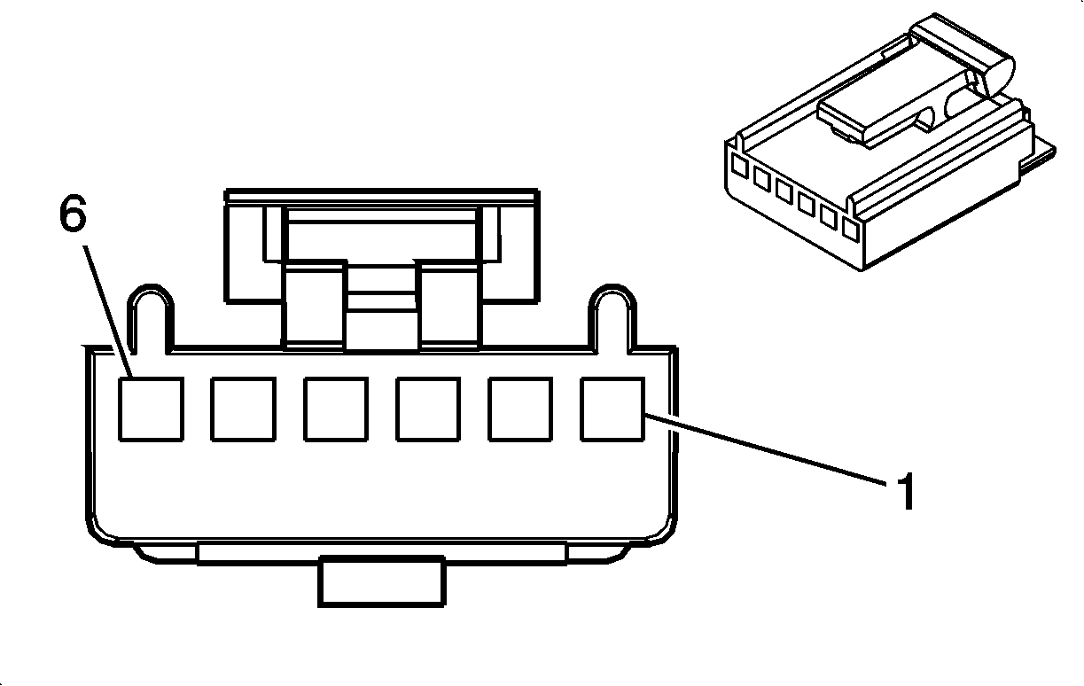
Connector Part Information |
| ||||||
Pin | Wire Color | Circuit No. | Function | ||||
1 | LT GRN/BLK | 366 | Defrost Mode Valve Solenoid Control | ||||
2 | RED | 362 | Lower Mode Valve Solenoid Control | ||||
3 | PPL | 361 | Mix-blend Mode Valve Solenoid Control | ||||
4 | TAN | 363 | Recirculation Mode Valve Solenoid Control | ||||
5 | LT BLU | 706 | Upper Mode Valve Solenoid Control | ||||
6 | BRN | 41 | Ignition 3 Voltage | ||||
| |||||||
|---|---|---|---|---|---|---|---|
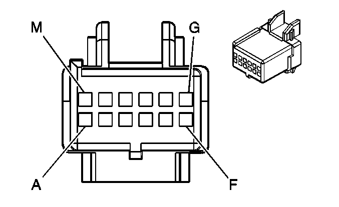
Connector Part Information |
| ||||||
Pin | Wire Color | Circuit No. | Function | ||||
A | ORN | 2212 | Rear A/C Control | ||||
B | PNK | 2216 | Rear A/C Request | ||||
C | BRN | 41 | Fused Ignition Feed | ||||
D - F | - | - | Not Used | ||||
G | YEL | 2214 | Rear Temp Control | ||||
H | DK GRN | 2211 | Rear Fan Up/Down Request | ||||
J | GRY | 8 | Interior Lamp Dim Signal | ||||
K | BLK | 1450 | Ground | ||||
L | RED | 2215 | Rear Air Flow Selector Control | ||||
M | DK BLU | 2213 | Rear Recirculation Control | ||||

| |||||||
|---|---|---|---|---|---|---|---|
Connector Part Information |
| ||||||
Pin | Wire Color | Circuit No. | Function | ||||
5 - 6 | - | - | Not Used | ||||
7 | BLK | 1450 | Ground | ||||
8 | RED | 2215 | Air Flow Selector Control | ||||
9 | - | - | Not Used | ||||
10 | BRN | 41 | Fused Ignition Feed | ||||
| |||||||
|---|---|---|---|---|---|---|---|
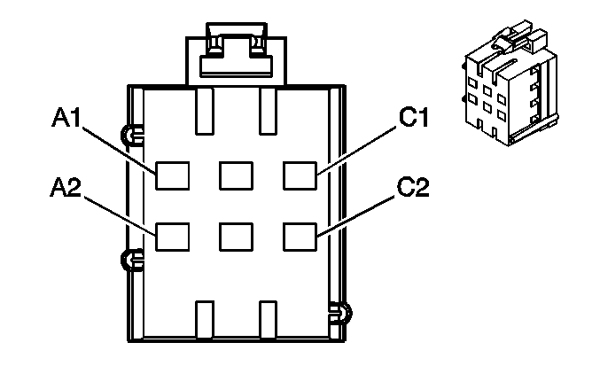
Connector Part Information |
| ||||||
Pin Flexlock | Wire Color | Circuit No. | Function | ||||
A1 | WHT | 2258 | Dual Stage Orifice Relay Output-Coil | ||||
A2 | BLK/WHT | 2256 | Dual Stage Orifice Solenoid Feed | ||||
B1-B2 | -- | -- | Not Used | ||||
C1 | BRN | 41 | Fuse Output-IGN 3 | ||||
C2 | BRN | 41 | Fuse Output-IGN 3 | ||||

| |||||||
|---|---|---|---|---|---|---|---|
Connector Part Information |
| ||||||
Pin | Wire Color | Circuit No. | Function | ||||
A | BLK/WHT | 2256 | Two Stage Orifice Solenoid Feed | ||||
B |
BLK | 1450 | Ground | ||||
