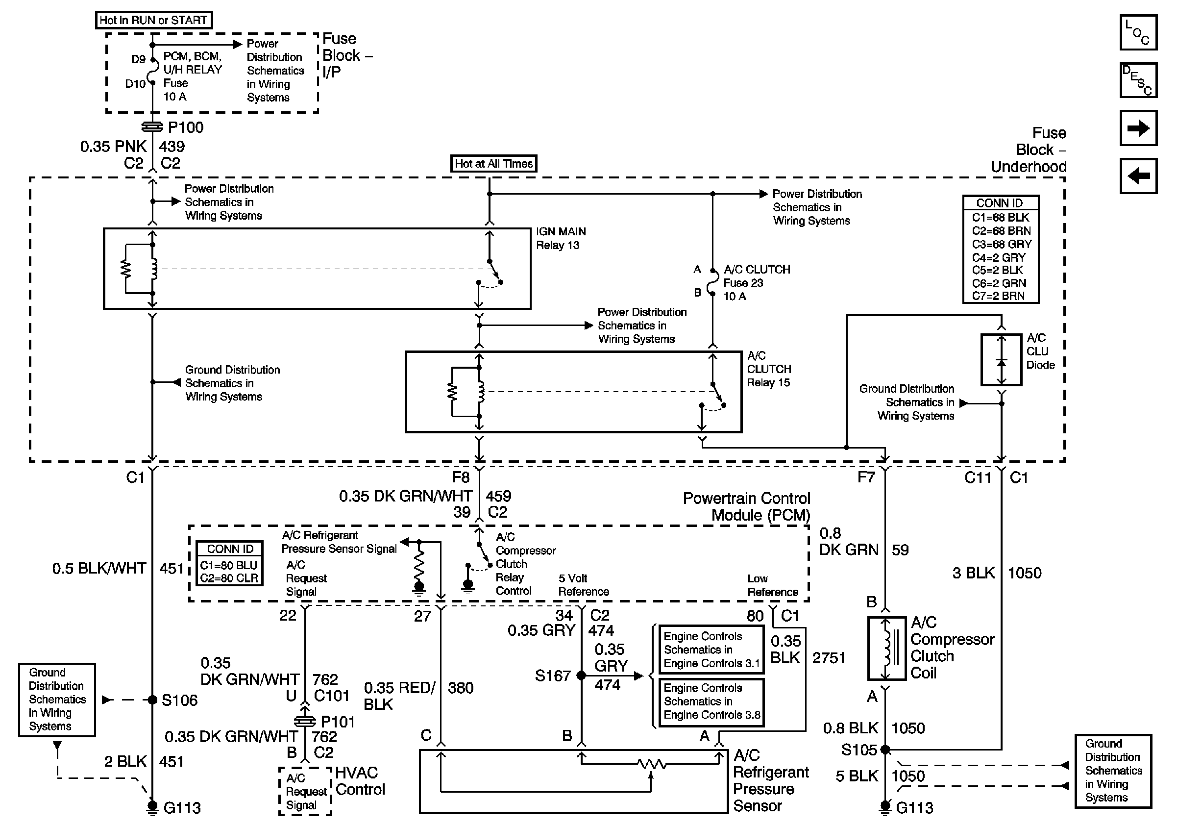
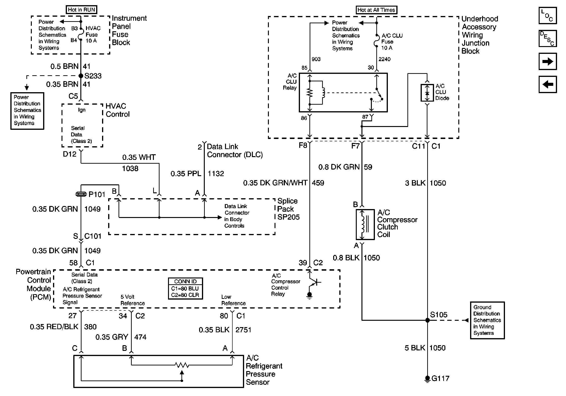
Refer to HVAC Schematic
Compressor Controls

and

for wiring diagrams.
Circuit Description
When A/C is selected through the A/C control head a signal is supplied
to the powertrain control module (PCM) A/C request circuit through the Class 2
Serial Data circuit on vehicle with CJ2 systems, on vehicles with C60 and
CJ3 systems the A/C control head supplies the signal to the PCM A/C request
circuit. The A/C relay is controlled through the PCM. The PCM monitors
the A/C refrigerant pressure. If the A/C refrigerant pressure, and engine
operating conditions are within specific calibrated acceptable ranges
the PCM will enable the A/C relay. This is accomplished by providing a
ground path for the A/C relay coil within the PCM. When the A/C compressor
relay is enabled battery positive voltage is supplied to the compressor
clutch coil.
The PCM will enable the A/C compressor clutch whenever the engine is
running and the A/C has been requested, unless any of the following conditions
are met:
VIN K
| • | Throttle angle is more than 96 percent. |
| • | A/C head pressure is more than 440 psi (4.6 volts)
or less than 32 psi (0.3 volt), as determined by the A/C refrigerant
pressure sensor. |
| • | Ignition 1 voltage is below 9.5 volts. |
| • | Engine speed is more than 4392 RPM for less than 1 second. |
| • | Engine speed is more then 4400 RPM for any amount of time. |
| • | ECT is more than 124°C (255°F). |
| • | IAT is less than 5°C (41°F). |
VIN 1
| • | Throttle angle is more than 96 percent. |
| • | A/C head pressure is more than 440 psi (4.6 volts)
or less than 35 psi (0.4 volt), as determined by the A/C refrigerant
pressure sensor. |
| • | Ignition 1 voltage is below 9.5 volts. |
| • | Engine speed is more then 4392 RPM for any amount of time. |
| • | ECT is more than 124°C (255°F). |
| • | IAT is less than 5°C (41°F). |
Any of the conditions described above will inhibit A/C compressor relay
operation.
Diagnostic Aids
Check for the following conditions:
| • | Poor connection at the PCM -- Inspect harness connectors
for: |
| - | Improperly formed or damaged terminals |
| - | Poor terminal to wire connection |
| • | Damaged harness -- Inspect the wiring harness for damage.
If the harness appears to be OK, disconnect the PCM, turn ON the ignition
and observe a voltmeter connected to the A/C relay control circuit
at the PCM harness connector while moving connectors and wiring
harnesses related to the A/C relay. A change in voltage
will indicate the location of the malfunction. |
Check for conditions that will disable A/C operation:
VIN K
| • | Throttle angle is more than 96 percent. |
| • | A/C head pressure is more than 440 psi (4.6 volts)
or less than 32 psi (0.3 volt), as determined by the A/C refrigerant
pressure sensor. |
| • | Ignition 1 voltage is below 9.5 volts. |
| • | Engine speed is more than 4392 RPM for less than 1 second. |
| • | Engine speed is more then 4400 RPM for any amount of time. |
| • | ECT is more than 124°C (255°F). |
| • | IAT is less than 5°C (41°F). |
VIN 1
| • | Throttle angle is more than 96 percent. |
| • | A/C head pressure is more than 440 psi (4.6 volts)
or less than 35 psi (0.4 volt), as determined by the A/C refrigerant
pressure sensor. |
| • | Ignition 1 voltage is below 9.5 volts. |
| • | Engine speed is more than 4392 RPM for any amount of time. |
| • | ECT is more than 124°C (255°F). |
| • | IAT is less than 5°C (41°F). |


