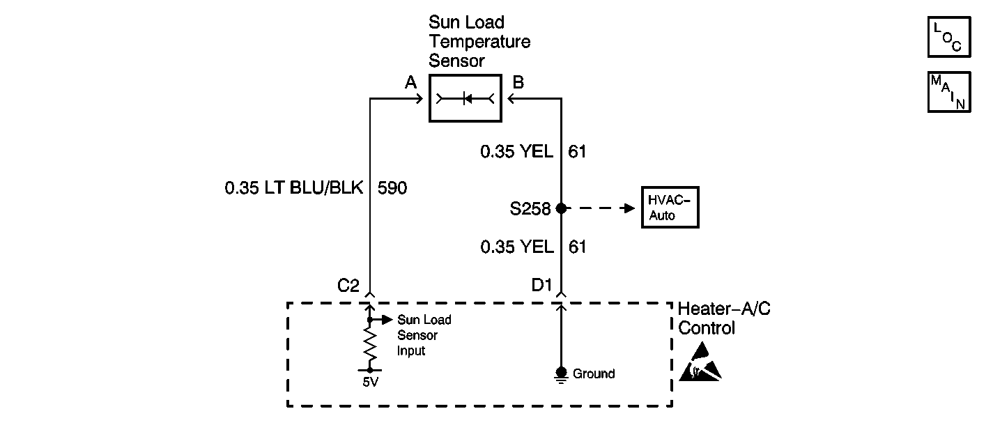
Circuit Description
The heater-A/C control determines the amount of sunlight produced by the sun through an input from the sun load temperature sensor. The heater-A/C control receives a voltage signal from the sun load temperature sensor through circuit 590 (LT BLU/BLK). The sun load temperature sensor is grounded by the heater-A/C control through circuit 61 (YEL).
As the sunlight increases, the electric current flowing through the sun load temperature sensor increases. When the heater-A/C control is in AUTO mode, the heater-A/C control uses the sun load temperature sensor information in order to control the blower speed and the BI-LEVEL modes.
Conditions for Setting the DTC
The heater-A/C control performs a check on the operation of the sun load temperature sensor and detects an open in circuit 590 (LT BLU/BLK).
Action Taken When the DTC Sets
The heater-A/C control stores DTC B0348 in memory.
Conditions for Clearing the DTC
| • | An open in circuit 590 (LT BLU/BLK) is no longer present. |
| • | Under all fault conditions, the ignition switch must be cycled from on to off, back to on before this DTC can change from current to history. |
| • | A history DTC clears after 100 drive cycles if a short to ground in circuit 590 (LT BLU/BLK) is no longer present. |
| • | Using a scan tool |
Diagnostic Aids
The following conditions may cause this DTC to set:
| • | A poor connection or open in circuit 590 (LT BLU/BLK) |
| • | A poor connection or open in circuit 61 (YEL) |
| • | A faulty sun load temperature sensor |
| • | A faulty heater-A/C control |
Test Description
The number(s) below refer to the step number(s) on the diagnostic table.
-
This step checks for proper voltage value at the sun load temperature sensor.
-
This step checks for a short to ground in 590 (LT BLU/BLK) .
Step | Action | Value(s) | Yes | No |
|---|---|---|---|---|
1 | Was the heater-A/C control diagnostic system check performed? | -- | Go to Step 2 | Go to Diagnostic System Check |
Is the measured voltage within the specified value? | 4.5-5.5V | Go to Step 3 | Go to Step 4 | |
3 |
Is the repair complete? | -- | Go to Step 7 | -- |
Is the measured resistance same as the specified value? | ∞ | Go to Step 6 | Go to Step 5 | |
5 | Locate and repair a short to ground in circuit 590 (LT BLU/BLK). Refer to Circuit Testing and Wiring Repairs in Wiring Systems. Is the repair complete? | -- | Go to Step 7 | -- |
6 | Replace the heater-A/C control. Refer to Control Assembly Replacement . Is the repair complete? | -- | Go to Step 7 | -- |
7 | Operate the system to verify that it operates properly. Does the system operate properly? | -- | System OK | Go to Diagnostic System Check |
