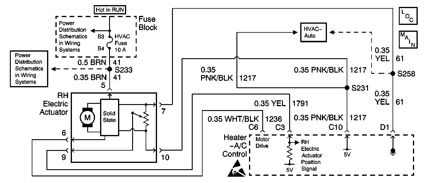
Circuit Description
The heater-A/C control receives a right electric actuator position signal from the right electric actuator. The right electric actuator position sensor is a potentiometer that is tied to a 5V source through circuit 1217 (PNK/BLK) and to ground through circuit 61 (YEL), both from the heater-A/C control. The variable output from the potentiometer feeds back a position signal through circuit 1791 (YEL) to a pull-up resistor in the heater-A/C control. This signal relates to the position of the right electric actuator. This signal is used in order to determine the necessary drive signal to the right electric actuator motor in order to provide the proper air mix door position.
Conditions for Setting the DTC
The heater-A/C control performs an internal check on the right electric actuator position and determines that circuit 1791 (YEL) is shorted to B+ or shorted to ground.
Action Taken When the DTC Sets
The heater-A/C control stores DTC B0365 in memory.
Conditions for Clearing the DTC
| • | A short to B+ or short to ground is no longer present in circuit 1791. |
| • | Under all fault conditions, the ignition switch must be cycled from on to off, back to on before this DTC can change from current to history. |
| • | A history DTC will clear after 100 drive cycles if the condition for this malfunction is no longer present. |
| • | Using a scan tool |
Diagnostic Aids
The following conditions may cause DTC B0365 to set:
| • | A short to ground in circuit 1217 (PNK/BLK) or circuit 1791 (YEL) |
| • | A short to B+ in circuit 61, circuit 1217, (PNK/BLK) or circuit 1791 (YEL) |
| • | An open in circuit 1217 (PNK/BLK) or circuit 1791 (YEL) |
Test Description
The number(s) below refer to the step number(s) on the diagnostic table.
-
This test checks if the heater-A/C control 5V supply is getting through circuit 1217 (PNK/BLK) .
-
This test checks if the heater-A/C control ground is getting through circuit 61(YEL).
-
This test checks if the heater-A/C control 5V supply is getting through circuit 1791(YEL) .
Step | Action | Value(s) | Yes | No |
|---|---|---|---|---|
1 | Was the heater-A/C control diagnostic system check performed? | -- | Go to Step 2 | Go to Diagnostic System Check |
Is the measured voltage within the specified range? | 4.5-5.5V | Go to Step 3 | Go to Step 6 | |
Use a DMM to measure the voltage between the RH electric actuator harness connector terminal 7 and terminal 10. Is the measured voltage within the specified range? | 4.5-5.5V | Go to Step 4 | Go to Step 9 | |
Use a DMM to measure the voltage between the RH electric actuator harness connector terminal 7 and terminal 9. Is the measured voltage within the specified range? | 4.5-5.5V | Go to Step 5 | Go to Step 12 | |
5 | Replace the RH electric actuator. Refer to Temperature Actuator Replacement (RH) . Is the repair complete? | -- | Go to Step 13 | -- |
6 | Check circuit 1217 (PNK/BLK) for a short to B+ or short to ground. Refer to Circuit Testing in Wiring Systems. Is there a short to B+ or short to ground in circuit 1217 (PNK/BLK)? | -- | Go to Step 7 | Go to Step 8 |
7 | Locate and repair the short to B+ or short to ground in circuit 1217 (PNK/BLK). Refer to Wiring Repairs in Wiring Systems. Is the repair complete? | -- | Go to Step 13 | -- |
8 |
Is the repair complete? | -- | Go to Step 13 | -- |
9 | Check circuit 61 (YEL) for a short to B+.Refer to Circuit Testing in Wiring Systems. Is there a short to B+ in circuit 61? | -- | Go to Step 10 | Go to Step 11 |
10 | Locate and repair a short to B+ in circuit 61(YEL). Refer to Circuit Testing in Wiring Systems. Is the repair complete? | -- | Go to Step 13 | -- |
11 |
Is the repair complete? | -- | Go to Step 13 | -- |
12 |
Is the repair complete? | -- | Go to Step 13 | -- |
13 | Verify that the system operates properly. Does the system operate properly? | -- | System OK | Go to Diagnostic System Check |
