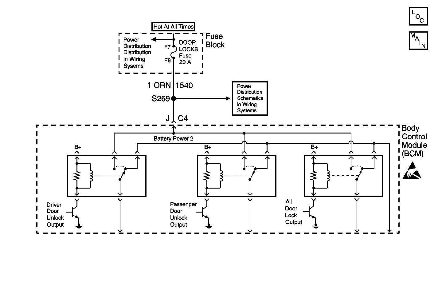
Circuit Description
The battery feed circuit, from the DOOR LOCKS fuse to the BCM, provides power for the door locks.
Conditions for Running the DTC
The voltage on the battery feed circuit, from the DOOR LOCKS fuse to the BCM must be between 9-16 volts.
Conditions for Setting the DTC
The BCM detects that the circuit from the DOOR LOCKS fuse to the BCM is less than 1 volt for longer than 0.3 seconds.
Action Taken When the DTC Sets
The BCM stores DTC B1334 in memory.
Conditions for Clearing the DTC
| • | A current DTC B1334 will clear if the BCM no longer detects the fault. |
| • | A history DTC B1334 will clear after 100 consecutive ignition cycles if the condition for the malfunction is no longer present. |
| • | Use a scan tool in order to clear the DTC. |
Diagnostic Aids
| • | If the DTC B1334 is a history DTC, the fault may be intermittent. Refer to Testing for Intermittent Conditions and Poor Connections in Wiring Systems. |
| • | The following conditions may cause an intermittent malfunction to occur: |
| - | An intermittent open in the circuit from the DOOR LOCKS fuse to the BCM. |
| - | The BCM is intermittently open internally. |
Test Description
The number(s) below refer to the step number(s) on the diagnostic table.
Step | Action | Value(s) | Yes | No |
|---|---|---|---|---|
1 | Did you perform the Body Control Module Diagnostic System Check? | -- | Go to Step 2 | |
2 |
Does the scan tool display Active for both parameters? | -- | Go to Diagnostic Aids | Go to Step 3 |
Test the battery circuit that does not display Active in the previous step for an open. Refer to Testing for Intermittent Conditions and Poor Connections and Connector Repairs in Wiring Systems. Did you find and correct the condition? | -- | Go to Step 6 | Go to Step 4 | |
4 | Inspect for poor connections at the harness connector of the Body Control Module. Refer to Testing for Intermittent Conditions and Poor Connections and Connector Repairs in Wiring Systems. Did you find and correct the condition? | -- | Go to Step 6 | Go to Step 5 |
5 |
Did you complete the repair? | -- | Go to Step 6 | -- |
6 |
Does the DTC reset? | -- | Go to Step 2 | System OK |
