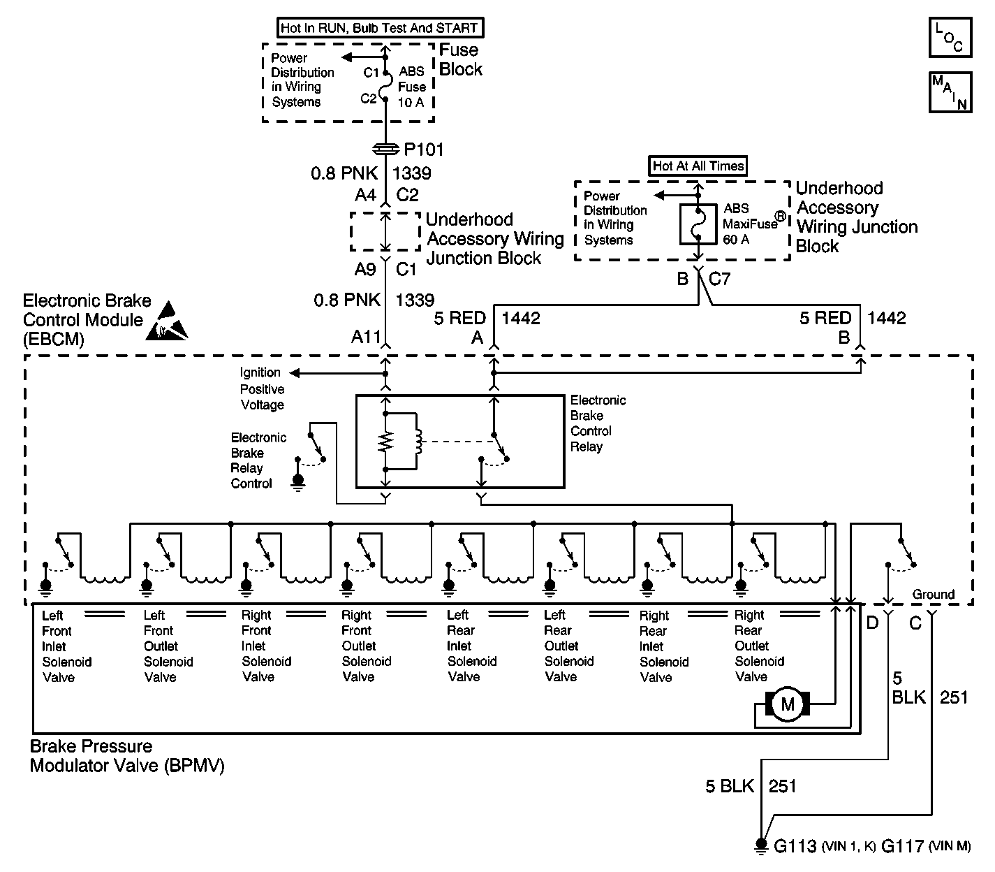
Circuit Description
The EBCM monitors the voltage at the Ignition Positive Voltage input and the Battery Positive Voltage circuit at the switch side of the Electronic Brake Control Relay. The voltage at the switch side of the Electronic Brake Control Relay is referred to as the system voltage. The EBCM uses both of the voltages in order to determine if a low voltage condition exists. A low voltage condition prevents the ABS/ETS/TCS system from operating properly.
Conditions for Running the DTC
| • | The vehicle speed is greater than 8 km/h (5 mph). |
| • | The ignition voltage is no more than 10.8 volts. |
| • | The electronic brake control relay is commanded ON. |
AND
Criteria 1
The ABS pump motor is OFF.
OR
Criteria 2
ABS is in initialization.
OR
Criteria 3
ABS or TCS is active.
Conditions for Setting the DTC
Either of the following criteria is present for greater than 0.72 seconds.
Criteria 1 and Criteria 2
The system voltage is no more than 10.8 volts.
OR
Criteria 3
The system voltage is no more than 9.36 volts.
Action Taken When the DTC Sets
| • | ABS/ETS/TCS is disabled. |
| • | ABS/ETS/TCS Indicators are turned on. |
Conditions for Clearing the DTC
| • | Condition for DTC is no longer present. |
| • | The Scan Tool clear DTC function is used. |
| • | 100 Ignition cycles have passed with no DTCs detected. |
Step | Action | Value(s) | Yes | No |
|---|---|---|---|---|
1 | Did you perform the ABS Diagnostic System Check? | -- | Go to Step 2 | |
2 |
Does the scan tool indicate the ignition voltage is greater than specified value? | 10.8 V | Go to Testing for Intermittent Conditions and Poor Connections | Go to Step 3 |
3 | With a scan tool, observe the Electronic Battery Feed parameter in the BCM data list. Does the scan tool indicate the electronic battery feed is greater than specified value? | 10.8 V | Go to Step 4 | Go to Battery Inspection/Test |
4 | Test the module ground circuit for an open or high resistance. Refer to Circuit Testing and Wiring Repairs in Wiring Systems. Did you find and correct the condition? | Go to Step 7 | Go to Step 5 | |
5 | Inspect for poor connections/terminal tension at the EBCM harness connector. Refer to Testing for Intermittent Conditions and Poor Connections and Connector Repairs in Wiring Systems. Did you find and correct the condition? | -- | Go to Step 7 | Go to Step 6 |
6 | Replace the EBCM. Refer to Electronic Brake Control Module Replacement Did you complete the replacement? | -- | Go to Step 7 | -- |
7 |
Does the DTC reset? | -- | Go to Step 2 | System OK |
