For 1990-2009 cars only
Tools Required
J-38125 Terminal Repair Kit
Removal Procedure
- Disconnect the negative battery cable. Refer to Battery Negative Cable Disconnection and Connection in Engine Electrical.
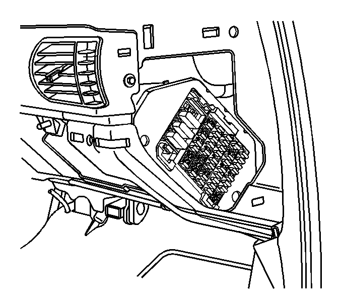
- Remove the access hole cover from the instrument panel (I/P) fuse block.
- Remove the right I/P insulator. Refer to Instrument Panel Insulator Panel Replacement - Right Side in Instrument Panel, Gages, and Console.
- Remove the I/P compartment. Refer to Instrument Panel Compartment Replacement in Instrument Panel, Gages, and Console.
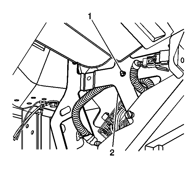
- Remove the lamp harness retainer (1) from the passenger knee bolster bracket (2).
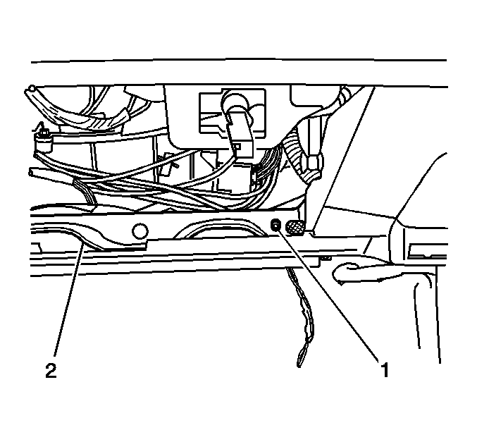
- Remove the wiring harness retainer (1) from the passenger knee bolster bracket (2).
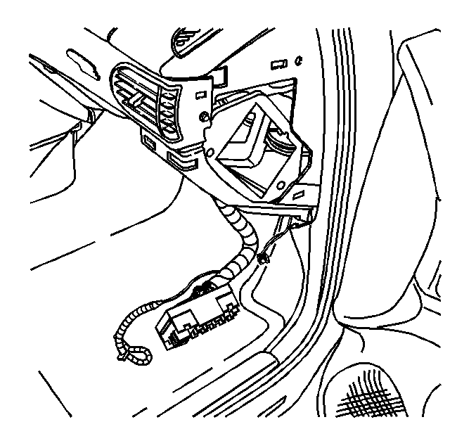
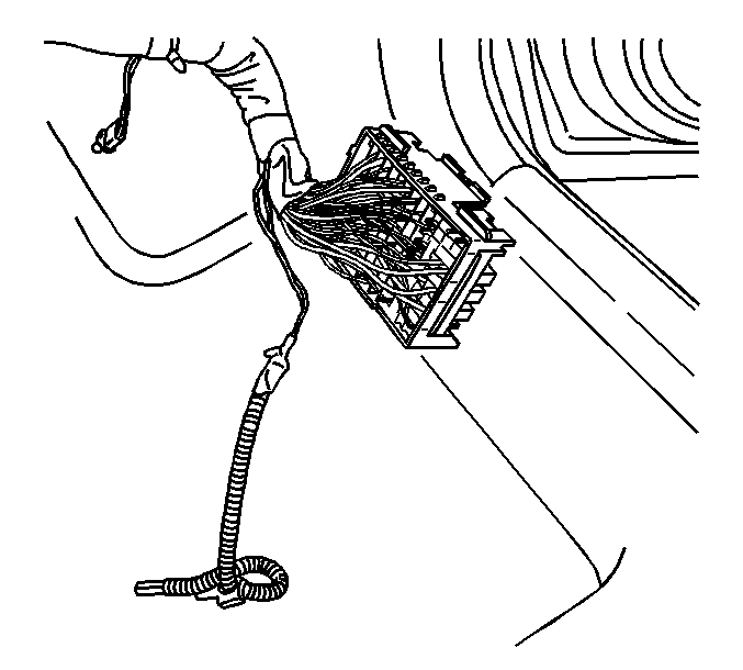
- Disengage the fuse block from the fuse block bracket on the body wiring harness. Lower the fuse block from the I/P.
- Remove the fuses and the relays from the fuse block. Refer to Electrical Center Identification Views .
- Use the correct terminal removal tool from J-38125 to remove the wires from the fuse block. Refer to Electrical Center Identification Views .
Installation Procedure
- Install the wires to the fuse block. Refer to Electrical Center Identification Views .
- Install the fuses and the relays to the fuse block. Refer to Electrical Center Identification Views .
- Position the fuse block to the I/P. Install the fuse block to the fuse block bracket on the body wiring harness.
- Install the wiring harness retainer (1) to the passenger knee bolster bracket (2).
- Install the lamp harness retainer (1) to the passenger knee bolster bracket (2).
- Install the I/P compartment. Refer to Instrument Panel Compartment Replacement in Instrument Panel, Gages, and Console.
- Install the right I/P insulator. Refer to Instrument Panel Insulator Panel Replacement - Right Side in Instrument Panel, Gages, and Console.
- Install the access hole cover to the I/P fuse block.
- Connect the negative battery cable. Refer to Battery Negative Cable Disconnection and Connection in Engine Electrical.


