| Table 1: | A/C Compressor Clutch |
| Table 2: | A/C Refrigerant Pressure Sensor |
| Table 3: | Air Temperature Actuator-Left |
| Table 4: | Air Temperature Actuator-Right |
| Table 5: | Blower Motor |
| Table 6: | Blower Motor Resistor Assembly |
| Table 7: | HVAC Control Module, C1 |
| Table 8: | HVAC Control Module, C2 |
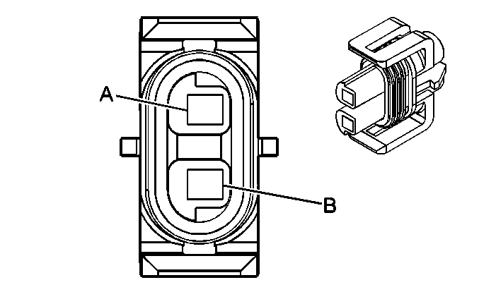
| |||||||
|---|---|---|---|---|---|---|---|
Connector Part Information |
| ||||||
Pin | Wire Color | Circuit No. | Function | ||||
A | BLK | 1050 | Ground | ||||
B | DK GRN | 59 | A/C Compressor Clutch Supply Voltage | ||||
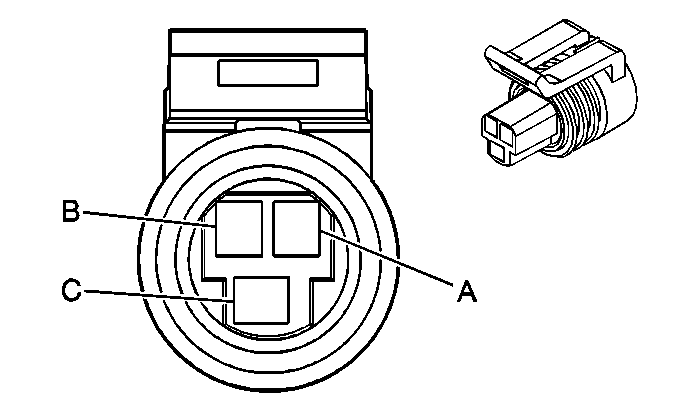
| |||||||
|---|---|---|---|---|---|---|---|
Connector Part Information |
| ||||||
Pin | Wire Color | Circuit No. | Function | ||||
A | BLK | 2751 | Low Reference | ||||
B | GRY | 474 | 5-Volt Reference | ||||
C | RED/BLK | 380 | A/C Refrigerant Pressure Sensor Signal | ||||
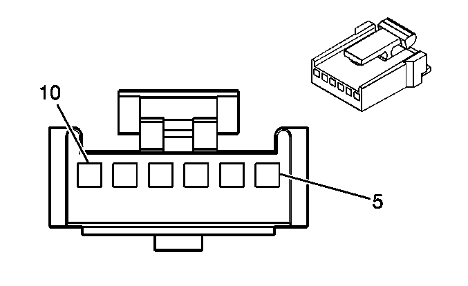
| |||||||
|---|---|---|---|---|---|---|---|
Connector Part Information |
| ||||||
Pin | Wire Color | Circuit No. | Function | ||||
5-6 | -- | -- | Not Used | ||||
7 | BLK | 1450 | Ground | ||||
8 | DK BLU | 1199 | Air Temperature Door Control | ||||
9 | -- | -- | Not Used | ||||
10 | BRN | 41 | Ignition 3 Voltage | ||||

| |||||||
|---|---|---|---|---|---|---|---|
Connector Part Information |
| ||||||
Pin | Wire Color | Circuit No. | Function | ||||
5-6 | -- | -- | Not Used | ||||
7 | BLK | 1450 | Ground | ||||
8 | WHT/BLK | 1236 | Right Air Temperature Door Control | ||||
9 | -- | -- | Not Used | ||||
10 | BRN | 41 | Ignition 3 Voltage | ||||
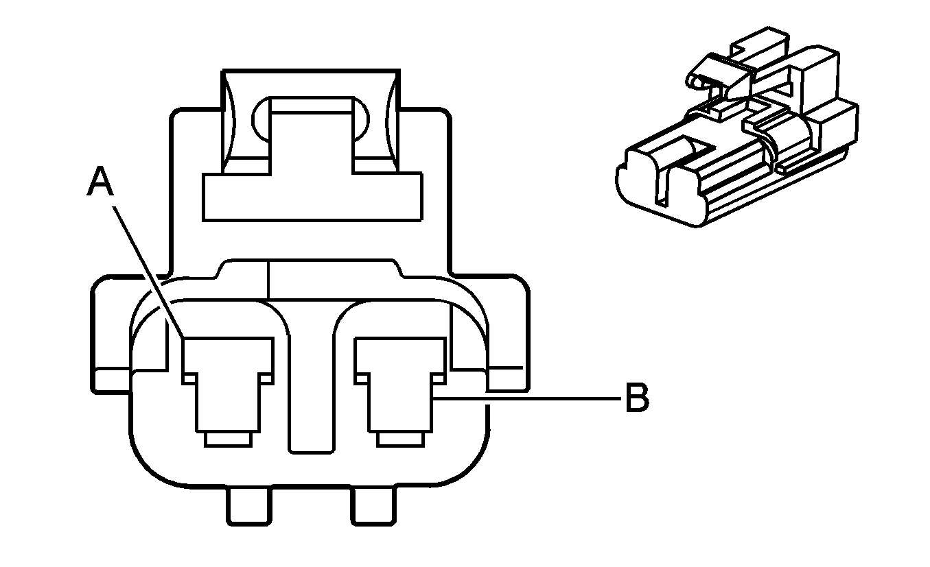
| |||||||
|---|---|---|---|---|---|---|---|
Connector Part Information |
| ||||||
Pin | Wire Color | Circuit Number | Function | ||||
A | PPL | -- | Blower Motor Supply Voltage | ||||
B | BLK | -- | Ground | ||||
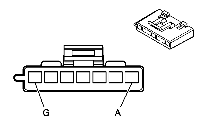
| |||||||
|---|---|---|---|---|---|---|---|
Connector Part Information |
| ||||||
Pin | Wire Color | Circuit No. | Function | ||||
A | TAN | 63 | Medium 1 Blower Motor Control | ||||
B | YEL | 60 | Low Blower Motor Control | ||||
C | PPL | 73 | Medium 3 Blower Motor Control | ||||
D | LT BLU | 72 | Medium 2 Blower Motor Control | ||||
E | BLK | 150 | Ground | ||||
F | ORN | 52 | High Blower Motor Control | ||||
G | ORN | 40 | Battery Positive Voltage | ||||
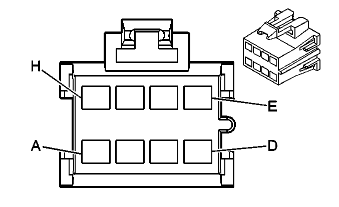
| |||||||
|---|---|---|---|---|---|---|---|
Connector Part Information |
| ||||||
Pin | Wire Color | Circuit No. | Function | ||||
A | DK GRN | 71 | Off Blower Motor Control | ||||
B | BRN | 141 | Ignition 3 Voltage | ||||
C | ORN | 52 | High Blower Motor Control | ||||
D | -- | -- | Not Used | ||||
E | PPL | 73 | Medium 3 Blower Motor Control | ||||
F | LT BLU | 72 | Medium 2 Blower Motor Control | ||||
G | TAN | 63 | Medium 1 Blower Motor Control | ||||
H | YEL | 60 | Low Blower Motor Control | ||||
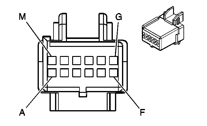
| |||||||
|---|---|---|---|---|---|---|---|
Connector Part Information |
| ||||||
Pin | Wire Color | Circuit No. | Function | ||||
A | DK GRN | 71 | Off Blower Motor Control | ||||
B | DK GRN/WHT | 762 | A/C Request Signal | ||||
C | BRN | 41 | Ignition 3 Voltage | ||||
D | WHT | 193 | Rear Defog Relay Control | ||||
E | WHT/BLK | 1236 | Right Air Temperature Door Control | ||||
F | -- | -- | Not Used | ||||
G | DK BLU | 1199 | Air Temperature Door Control | ||||
H | -- | -- | Not Used | ||||
J | GRY | 8 | Instrument Panel Lamps Dimmer Switch Signal | ||||
K | BLK | 1450 | Ground | ||||
L | ORN | 640 | Battery Positive Voltage | ||||
M | YEL | 32 | Instrument Panel Lamp Fuse Supply Voltage - 1 | ||||
