Front Case Half
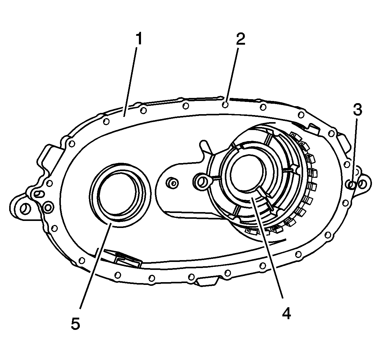
- Clean the front case half
in cleaning solvent and air dry.
- Remove the shavings from the case half bolt holes.
Notice: Refer to Machined Surface Damage Notice in the Preface section.
- Remove the sealer from the case sealing surfaces.
- Inspect the case for being broken or cracked.
- Inspect the front output shaft front bearing bore (5) for
the following conditions:
- Inspect the input shaft bearing bore (4) for the following
conditions:
- Replace the front case half if any of the above conditions are
found.
- Inspect the sealing surfaces (1) for damage.
- Repair small scratches or nicks with a soft stone.
- Inspect the front case to transmission case mounting surface for
damage.
- Inspect the case threaded bolt holes (2) for damage.
- Repair any damaged threads.
- Inspect the transmission to transfer case studs for damage.
- Replace any damaged studs. Refer to
Transfer Case Disassemble
and
Transfer Case Assemble
.
- Inspect the location pins (3) for being loose or missing.
- Repair or replace any damaged location pins.
- Inspect the front output shaft front bearing and the input shaft
bearing for the following conditions:
- Replace the bearings if any of the above conditions are found.
Refer to
Transfer Case Disassemble
and
Transfer Case Assemble
.
Rear Case Half
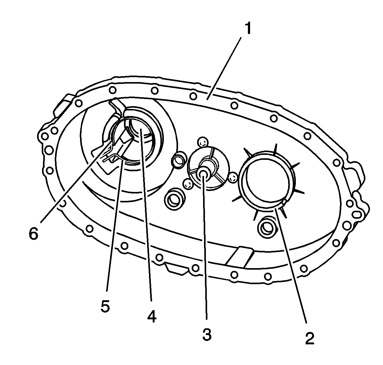
- Clean the rear case half
in cleaning solvent and air dry.
Notice: Refer to Machined Surface Damage Notice in the Preface section.
- Remove the sealer from the case sealing surfaces.
- Inspect the case for being broken or cracked.
- Replace the case if it is broken or cracked.
- Inspect the sealing surfaces (1) for damage.
- Repair small scratches or nicks with a soft stone.
- Inspect the case threaded bolt holes for damage.
- Repair any damaged threads.
- Inspect the front output shaft rear bearing bore (2) for
the following conditions:
- Inspect the rear output shaft rear bearing bore (5) for
the following conditions:
- Replace the case if the bearing has spun. Refer to
Transfer Case Disassemble
and
Transfer Case Assemble
.
- Inspect the retaining ring (6) for the rear output shaft
rear bearing for being bent or twisted.
- Replace a faulty retaining ring.
- Inspect the rear output shaft bushing (4) for scoring or
wear.
- Replace the case if the rear output shaft bushing is faulty. Refer
to
Transfer Case Disassemble
and
Transfer Case Assemble
.
- Inspect the shift detent lever shaft bore (3) for the
following conditions:
- Replace the case if the shift detent lever shaft bore is faulty.
Refer to
Transfer Case Disassemble
and
Transfer Case Assemble
.
Oil Pump
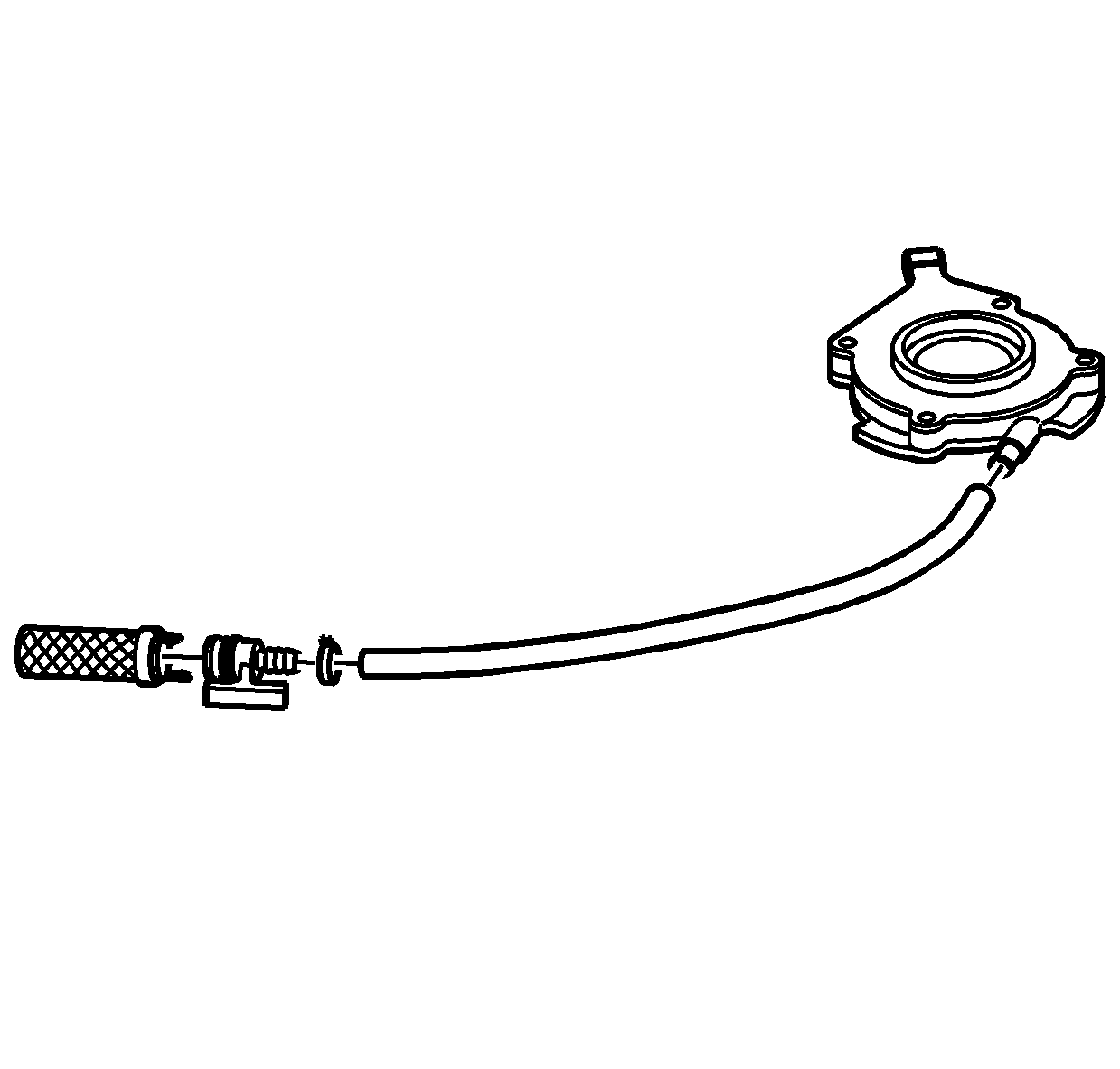
- Remove the oil pump suction
hose from the oil pump screen.
- Clean the hose and screen in cleaning solvent and air dry.
- If the screen is embedded with debris, replace the screen.
- Inspect the hose for cracking or tears.
- Replace the hose if it is faulty.
- Inspect the oil pump for free movement.
- Replace the oil pump if there is any binding. Do not disassemble
the oil pump. The oil pump is serviced as a unit.
- Inspect the wear clip on the oil pump.
- Replace the oil pump if the wear clip is missing or faulty.
High/Low Range Components
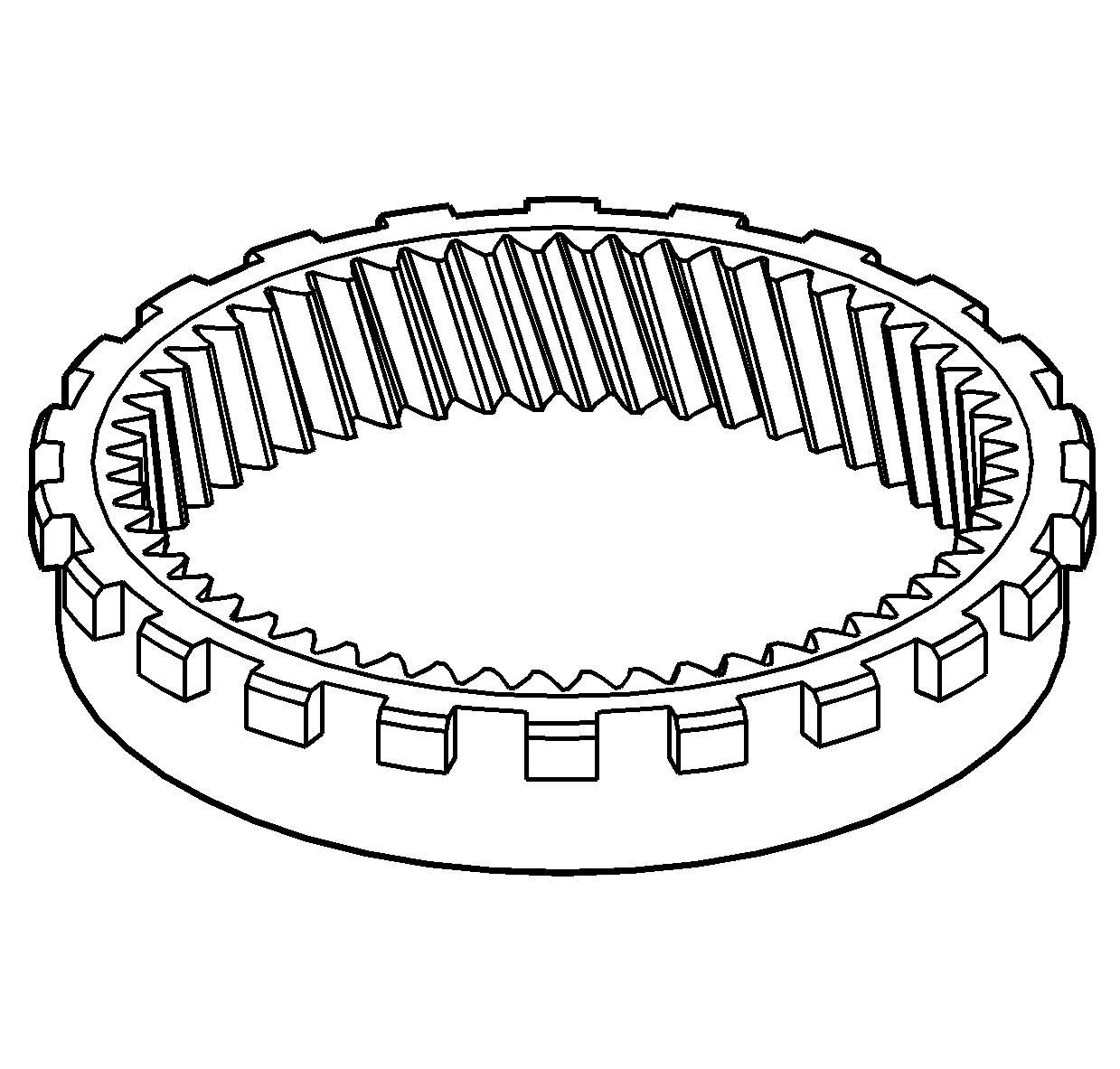
- Clean the annulus gear
in cleaning solvent and air dry.
- Inspect the annulus gear teeth for the following conditions:
| • | Damage or excessive wear |
| • | Debris embedded in the root of the teeth |
- Replace the annulus gear if it is faulty.
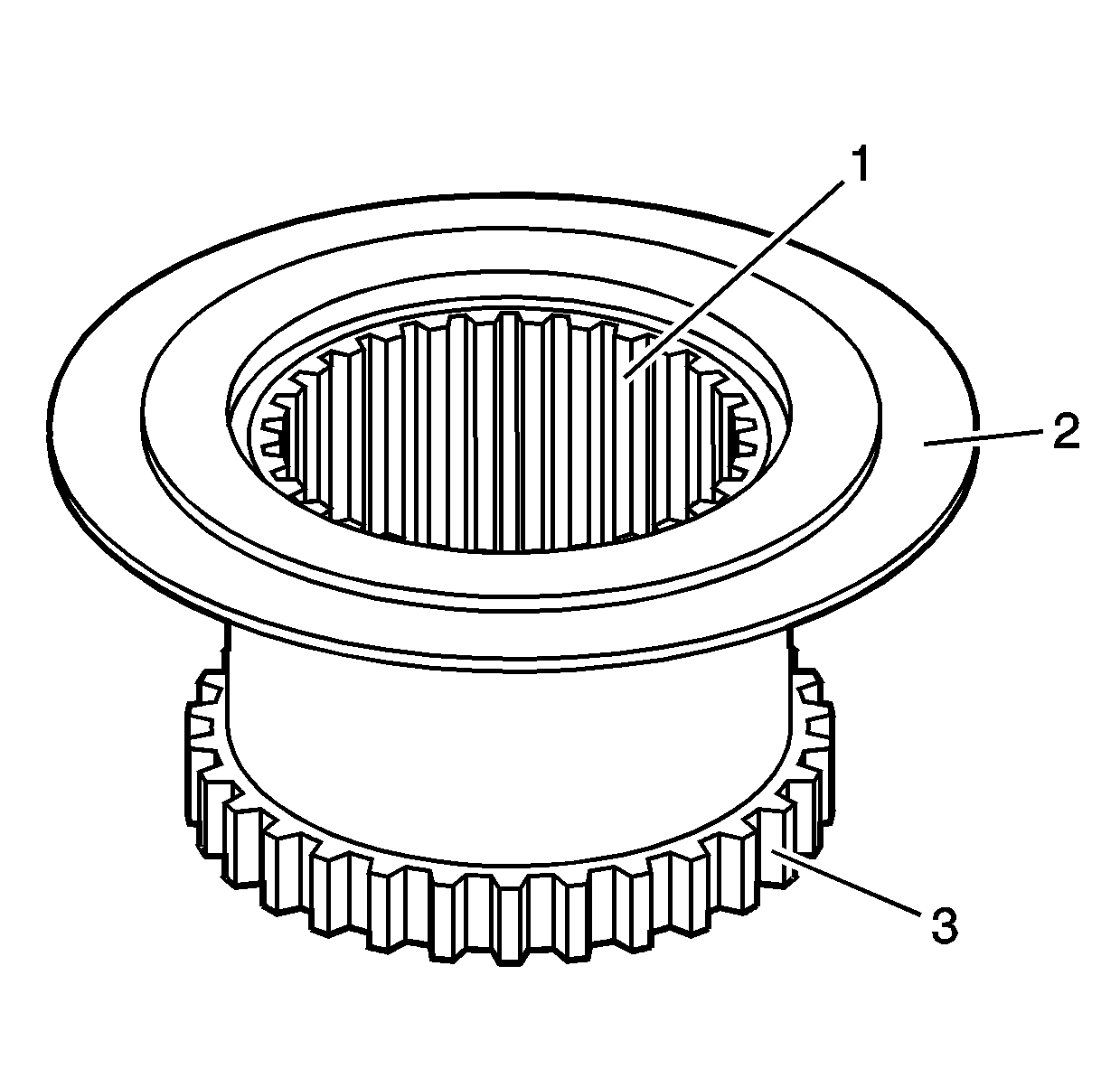
- Clean the high/low range
shift sleeve in cleaning solvent and air dry.
- Inspect the high/low range shift sleeve for the following conditions:
| • | Excessive wear or roughness on the shift fork pad surface (2) |
| • | Damaged, chipped or excessive wear on the engagement teeth (3) |
| • | Excessive looseness or gouging on the mainshaft splines (1) |
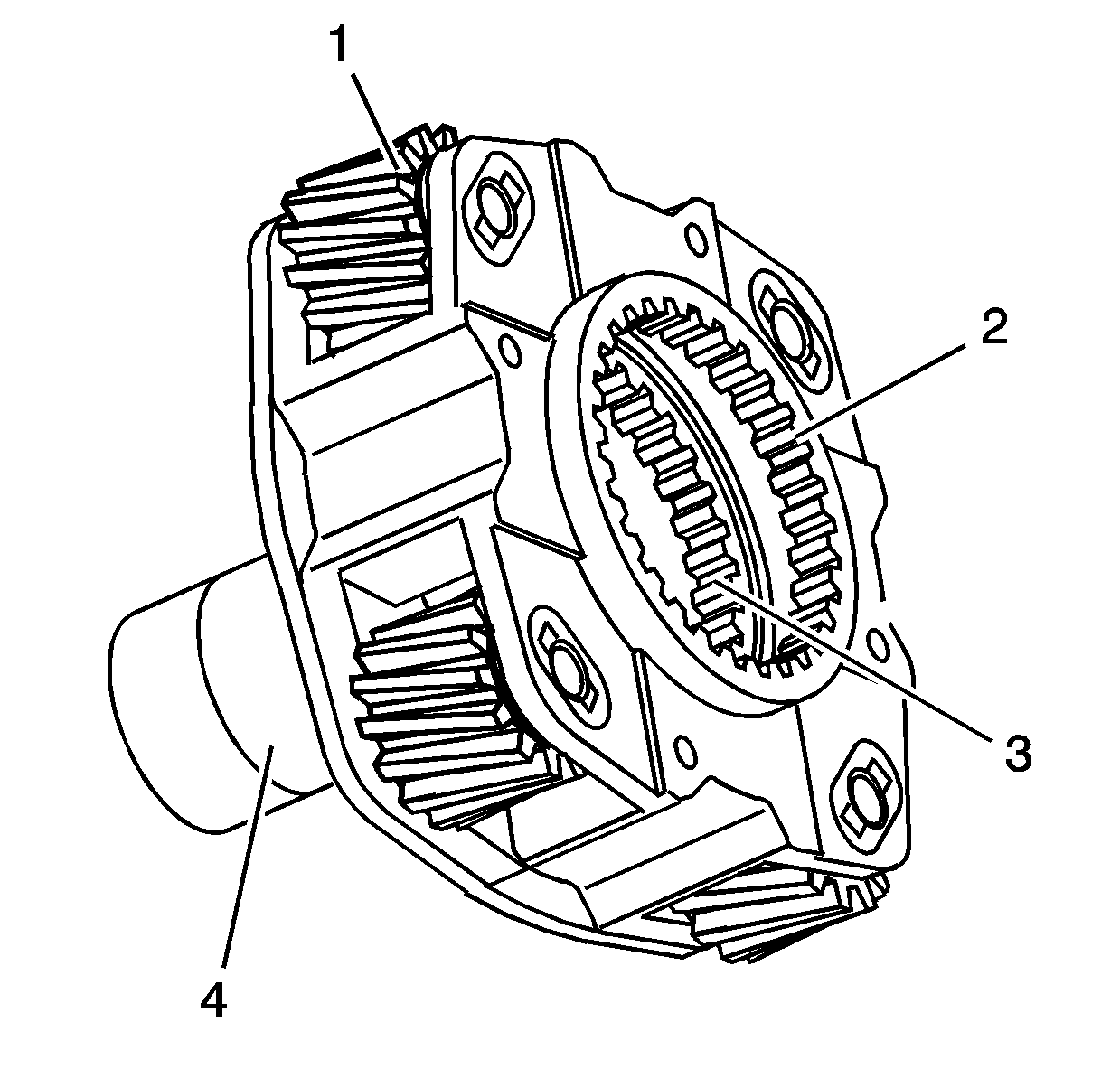
- Clean the high/low planetary
carrier in cleaning solvent. Do not disassemble the planetary carrier.
- Air dry and ensure all cleaning solvent is removed from the bearings
in the planetary gears (1). Do not spin the planetary gears
with compressed air.
- Inspect the planetary gears for chipped teeth.
- Inspect the planetary gears for debris embedded in the root of
the teeth.
- Inspect the planetary gears for excessive side movement from worn
bearings or shafts.
- Inspect the low range teeth (2) for damage or excessive
wear.
- Inspect the high range teeth (3) for damage or excessive
wear.
- Inspect the input seal surface (4) for scoring or excessive
wear.
- Inspect the thrust washer surface for scoring or excessive wear.
- Replace the high/low planetary carrier if any of the above conditions
are found.
- Inspect the mainshaft front support bearing for the following
conditions:
- Replace the mainshaft front support bearing if it is faulty. Refer
to
Transfer Case Disassemble
and
Transfer Case Assemble
.
- Inspect the high/low planetary thrust washer for excessive wear
or scoring.
- Replace the thrust washer if it is faulty.
Differential Components
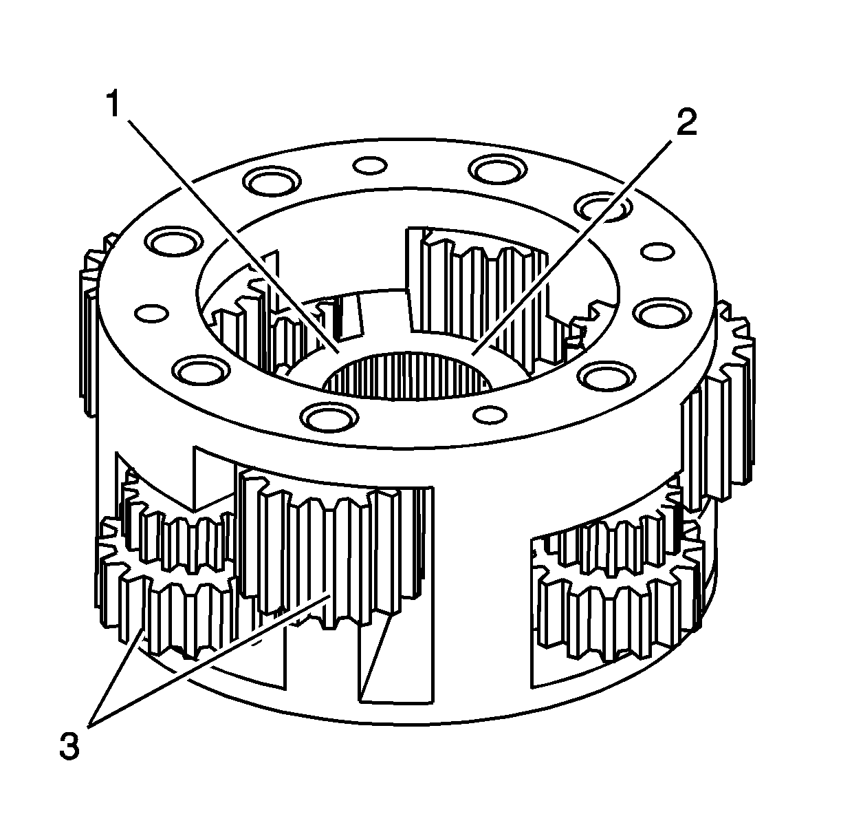
- Clean the planetary differential
in cleaning solvent. Do not disassemble the planetary differential.
- Air dry and ensure all cleaning solvent is removed from the bushings
in the pinion gears (3). Do not spin the pinion gears with
compressed air.
- Inspect the pinion gears for chipped teeth.
- Inspect the pinion gears for debris embedded in the root of
the teeth.
- Inspect the pinion gears for excessive side movement from worn
bushings or shafts.
- Inspect the planetary differential assembly for cracks at the
web (1) of the housing.
- Inspect the thrust washer surface (2) for scoring or excessive
wear.
- Inspect the planetary differential for distortion.
- Inspect the planetary differential to mainshaft splines for excessive
wear.
- Replace the planetary differential if any of the above conditions
are found.
- Inspect the thrust washers for excessive wear or scoring.
- Replace the thrust washers if they are faulty.
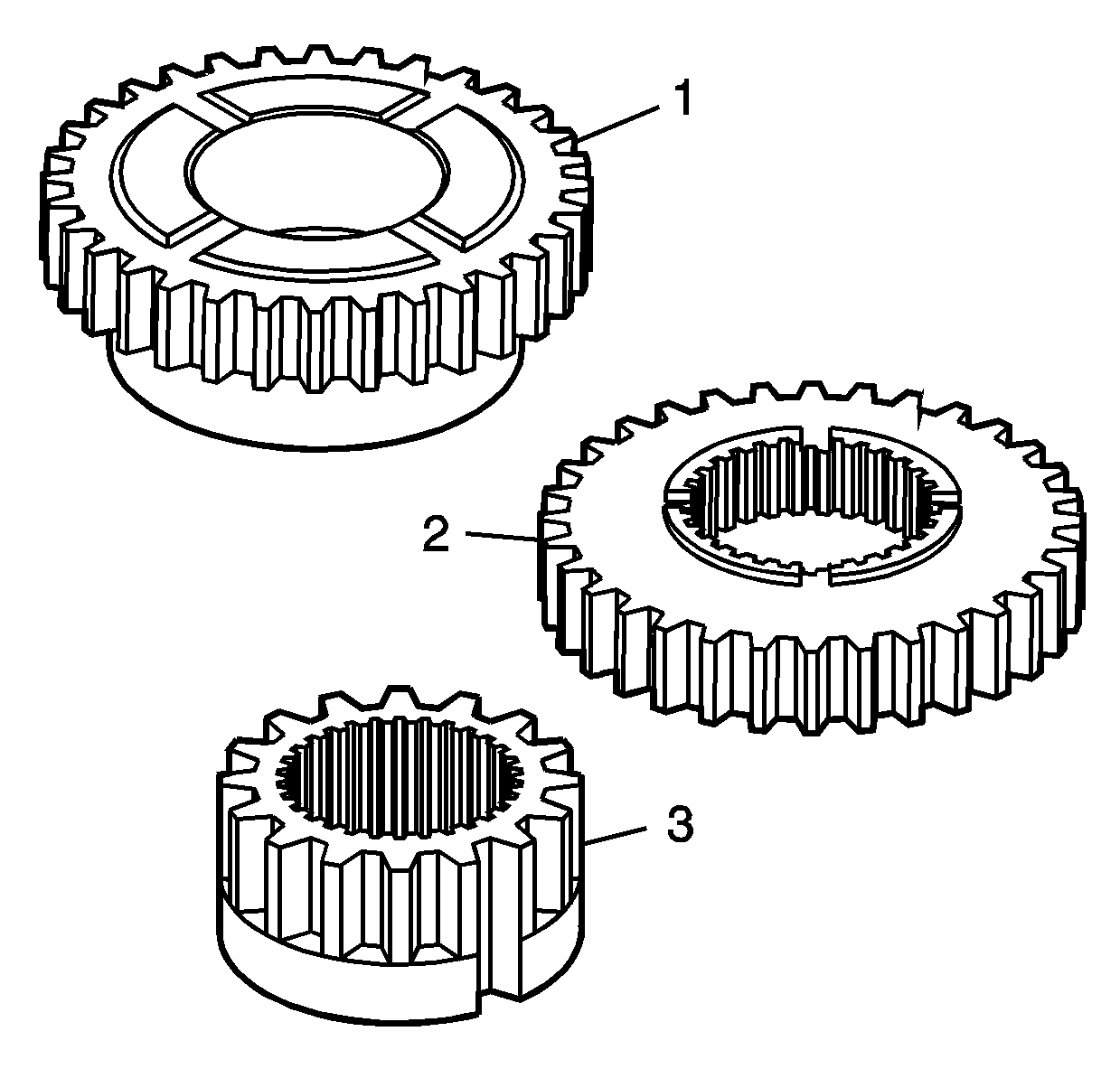
- Clean the front sun gear (1),
the rear sun gear (2), and the inner lockup hub (3) in
cleaning solvent and air dry.
- Inspect the teeth on the front sun gear (1), the rear
sun gear (2), and the inner lockup hub (3) for the following
conditions:
| • | Excessively worn gear surfaces |
| • | Slight wear marks are
normal. |
| • | Debris embedded in the root of the teeth |
- Inspect the thrust washer surfaces for excessive wear or scoring.
- Replace the front sun gear (1), the rear sun gear (2),
and the inner lockup hub (3) if they are faulty.
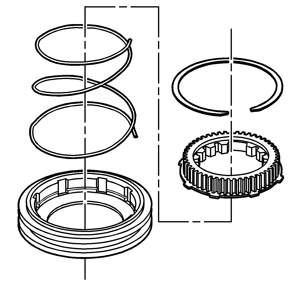
- If necessary, disassemble
the lockup shift assembly. Refer to
Transfer Case Disassemble
and
Transfer Case Assemble
.
- Clean the lockup shift assembly components in cleaning solvent
and air dry.
- Inspect the lockup shift hub engagement teeth for the following
conditions:
| • | Excessively worn gear surfaces |
| • | Slight wear marks are
normal. |
| • | Debris embedded in the root of the teeth |
- Replace the lockup shift assembly if it is faulty. The lockup
shift assembly components are not serviced separately.
Drive Chain and Sprockets
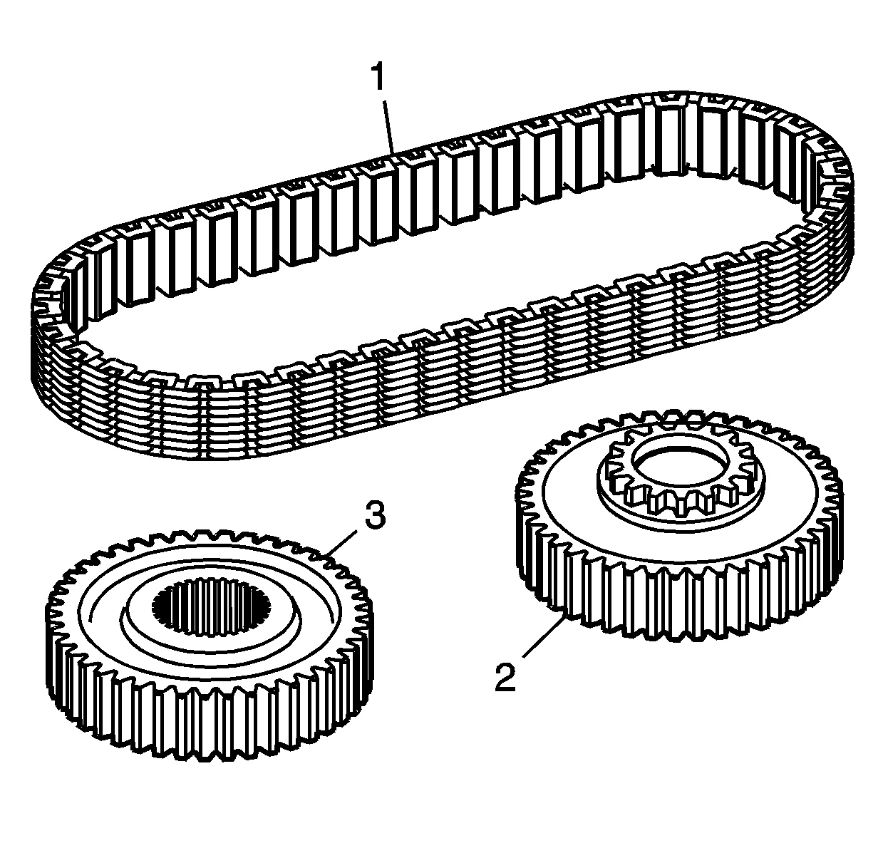
- Clean the drive chain (1),
drive sprocket (2), and driven sprocket (3) in cleaning
solvent and air dry.
- Inspect the drive chain (1) for the following conditions:
| • | Debris embedded in the links |
- Replace the chain if any of the above conditions are found.
- Inspect the driven sprocket (3) and the drive sprocket (2)
for the following conditions:
| • | Excessively worn gear surfaces |
| • | Slight wear marks are
normal. |
| • | Debris embedded in the root of the teeth |
- Inspect the drive sprocket (2) for the following conditions:
| • | Lockup shift engagement teeth for chipping |
| • | Lockup shift engagement teeth for excessive wear |
- Inspect the drive sprocket bushing for the following conditions:
- Replace the sprockets if any of the above conditions are found.
The chain and sprockets may be replaced separately.
Mainshaft
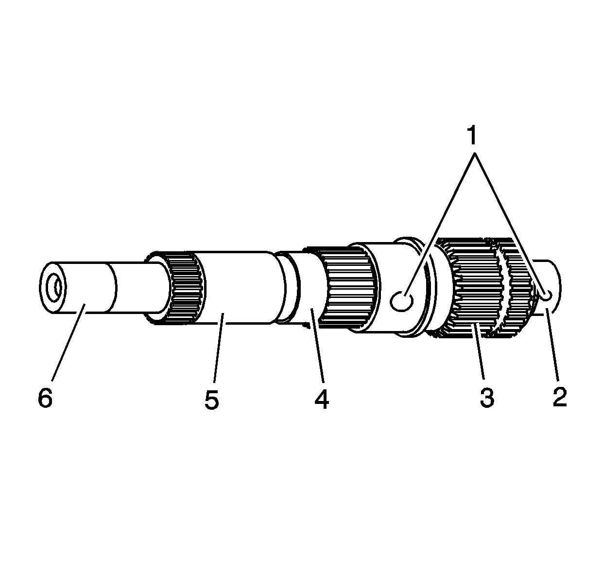
- Clean the mainshaft in
cleaning solvent.
- Clean the mainshaft oil galleries (1) and air dry.
Important: Do not attempt to smooth any roughness in the bearing journals.
- Inspect the bearing journals on the mainshaft for the following conditions:
| • | The front support bearing (2) |
| • | The drive gear bushing (4) |
| • | The rear support bushing (6) |
- Inspect the mainshaft range collar splines (3) for damage
or excessive wear. Witness marks at the location of the gear is normal.
- Replace the mainshaft if any of the above conditions are found.
Front Output Shaft
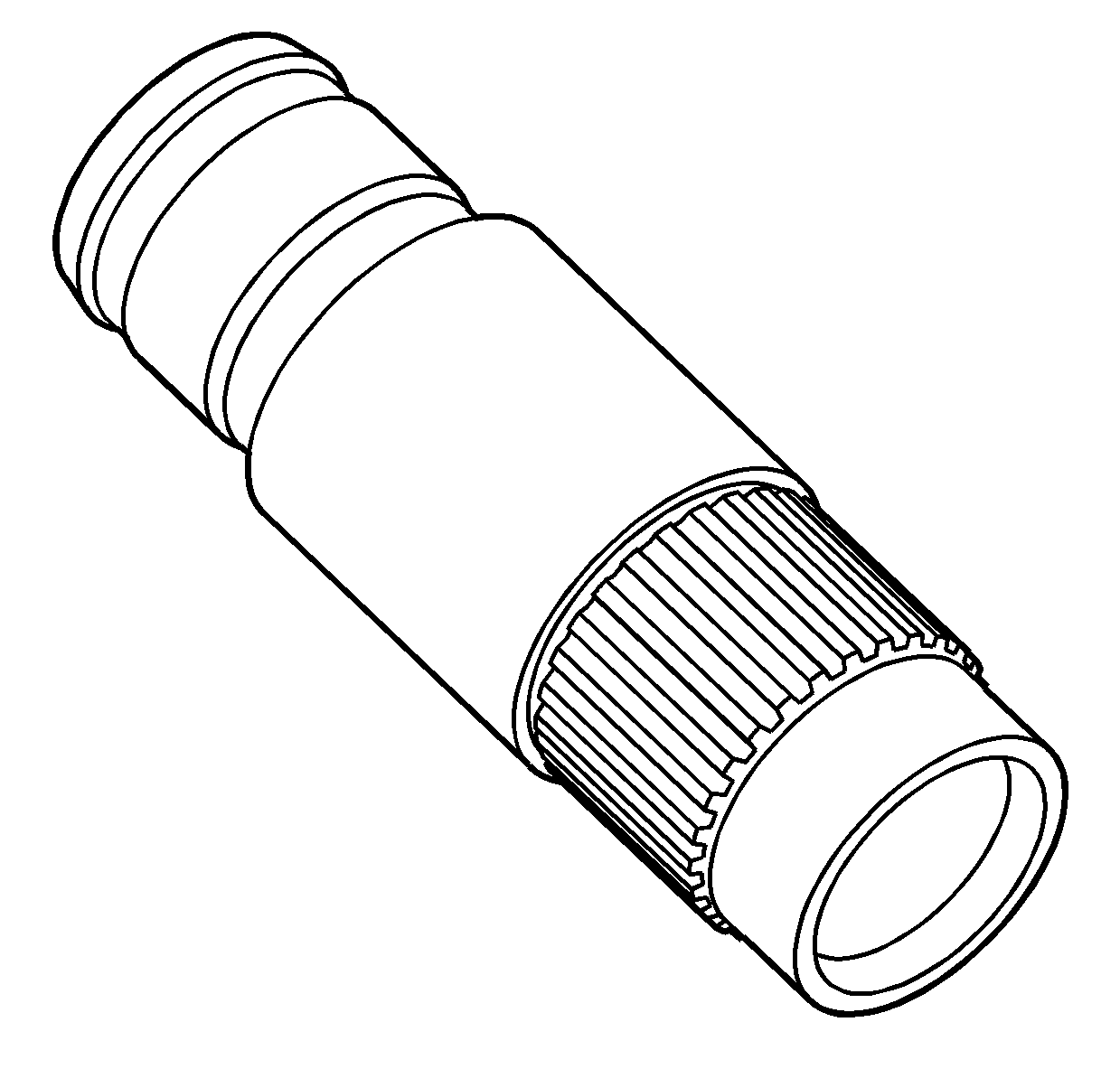
- Clean the front output
shaft in cleaning solvent and air dry.
- Inspect for spun bearings at the front output shaft bearing areas.
- Inspect the front output internal splines and driven gear splines
for damage or excessive wear.
- Replace the front output shaft if it is damaged.
- Inspect the cup plug in the front output shaft for leaking.
- Replace the cup plug if it is leaking. Refer to
Transfer Case Disassemble
and
Transfer Case Assemble
.
Rear Output Shaft
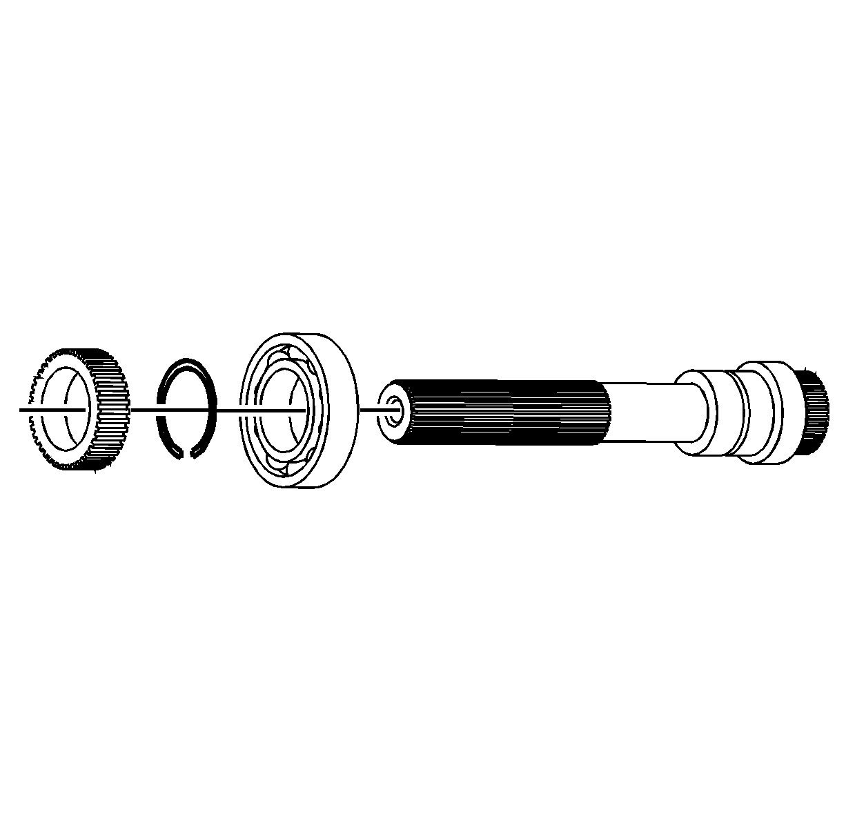
- Clean the rear output
shaft with rear output shaft bearing in cleaning solvent.
- Air dry and ensure all solvent is removed from the bearing.
- Inspect the speed reluctor wheel for damage.
- Replace the speed reluctor wheel if it is faulty. Refer to
Transfer Case Disassemble
and
Transfer Case Assemble
.
- Inspect the rear output shaft bearing for the following conditions:
- Replace the rear output shaft bearing if it is faulty. Refer to
Transfer Case Disassemble
and
Transfer Case Assemble
.
- Inspect the mainshaft rear support bushing for the following conditions:
- Replace the mainshaft rear support bushing if any of the above
conditions are found. Refer to
Transfer Case Disassemble
and
Transfer Case Assemble
.
- Inspect the rear output shaft splines for wear or damage.
- Inspect the rear output shaft bearing area for a spun bearing.
- Replace the rear output shaft if any of the above conditions are
found.
Shift System Components
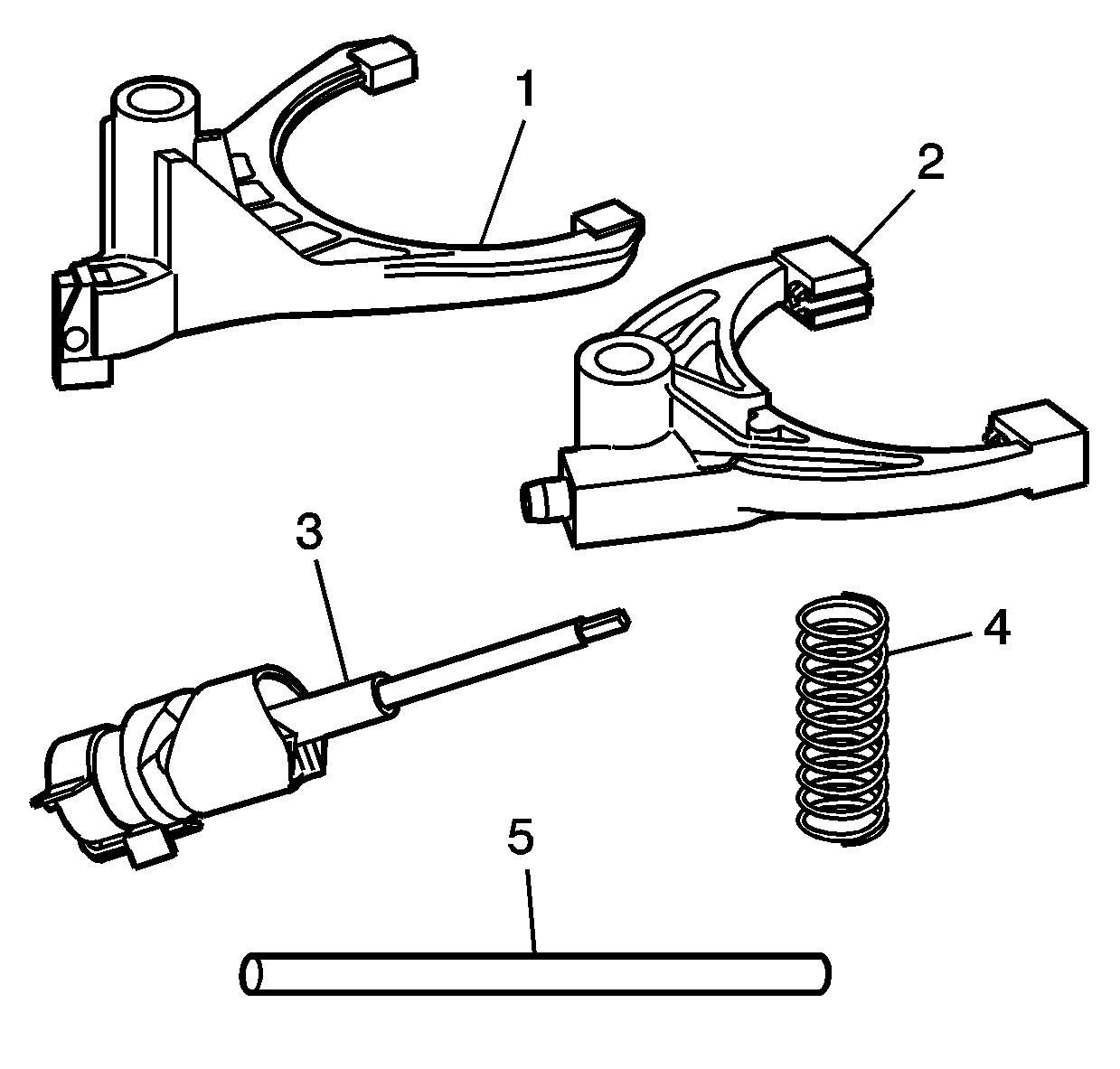
- Clean the following shift
system components in cleaning solvent and air dry.
| • | The lockup mode shift fork (1) |
| • | The high/low range shift fork (2) |
| • | The shift detent lever shaft assembly (3) |
| • | The shift fork spring (4) |
| • | The shift fork shaft (5) |
- Inspect the shift fork shaft (5) for straightness and excessive
wear at the shift fork locations.
- Replace the shift fork shaft if it is not straight or if it is
worn excessively.
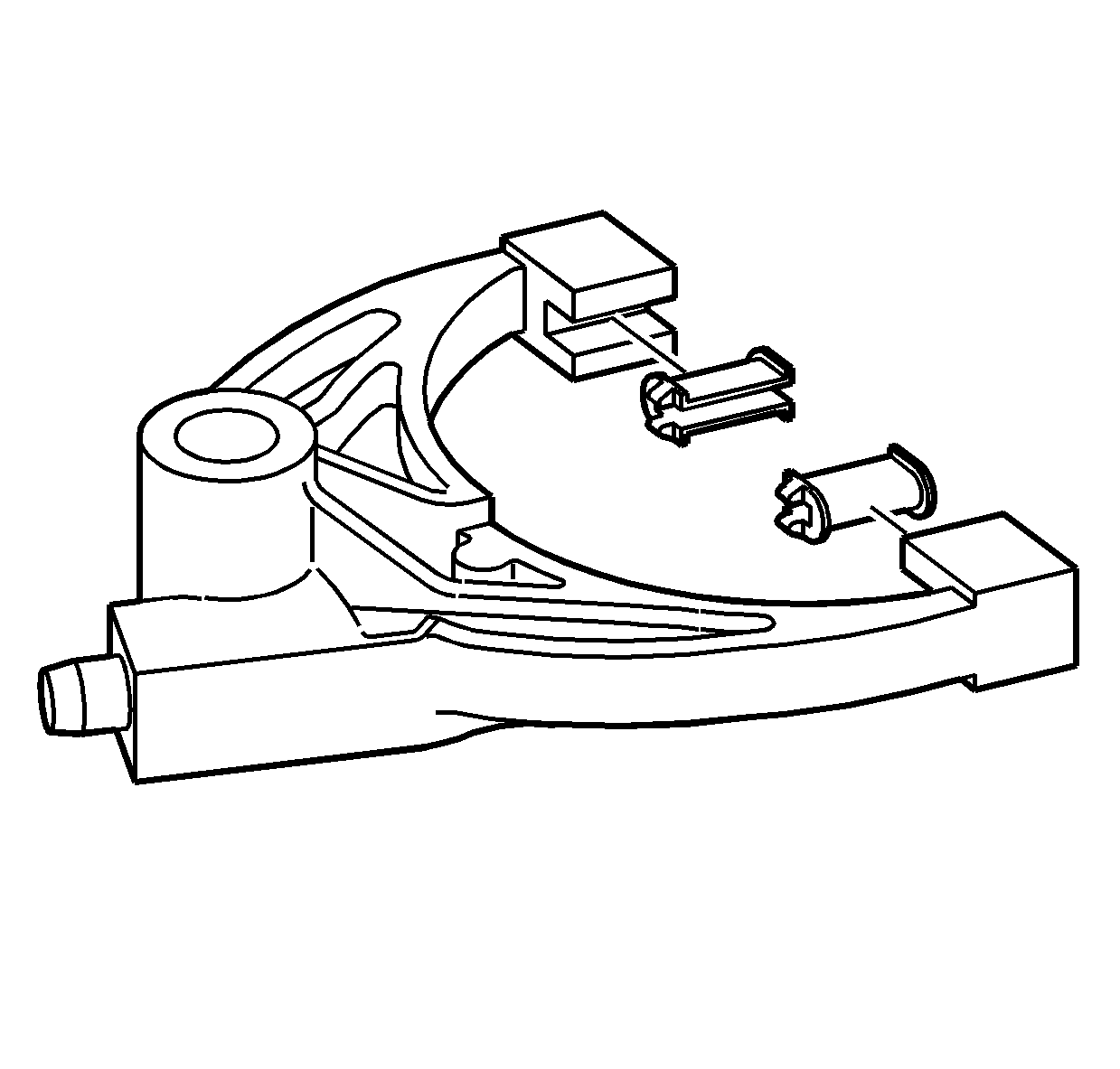
- Inspect the pads on the
high/low range shift fork for wear.
- Replace the worn pads.
- Inspect the roller on the shift fork for wear.
- Inspect the bore for the shift fork shaft for excessive wear.
- Replace the shift fork if the above conditions are found.
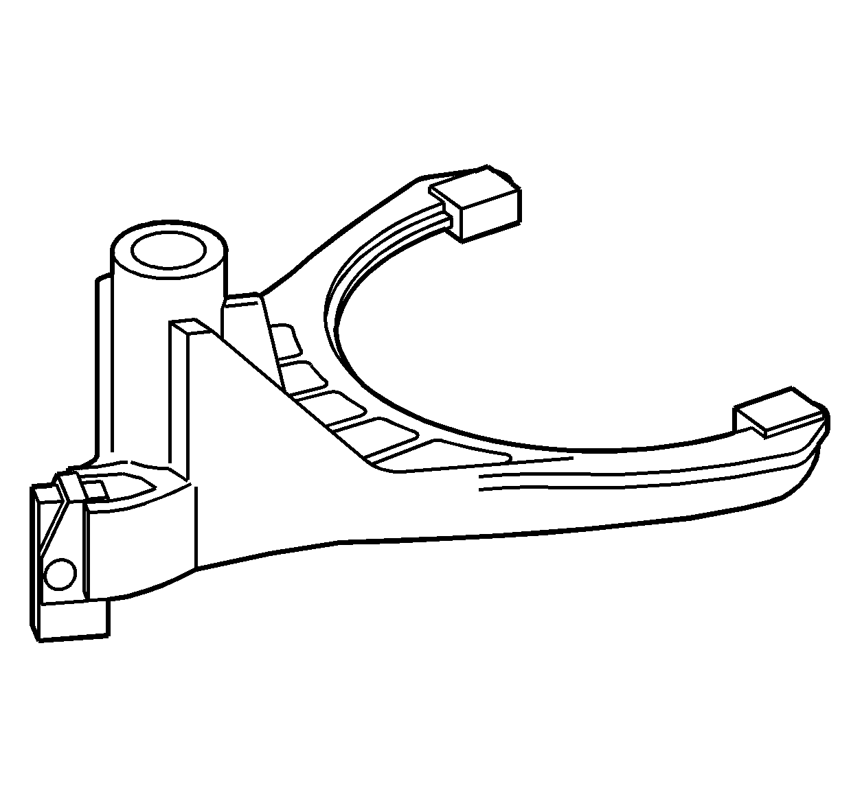
- Inspect the lockup mode
shift fork for excessive wear at the lockup collar pads.
- Inspect the lockup mode shift fork for wear at the shift detent
cam follower.
- Inspect the lockup mode shift fork for cracks.
- Replace the lockup mode shift fork if any of the above conditions
are found.
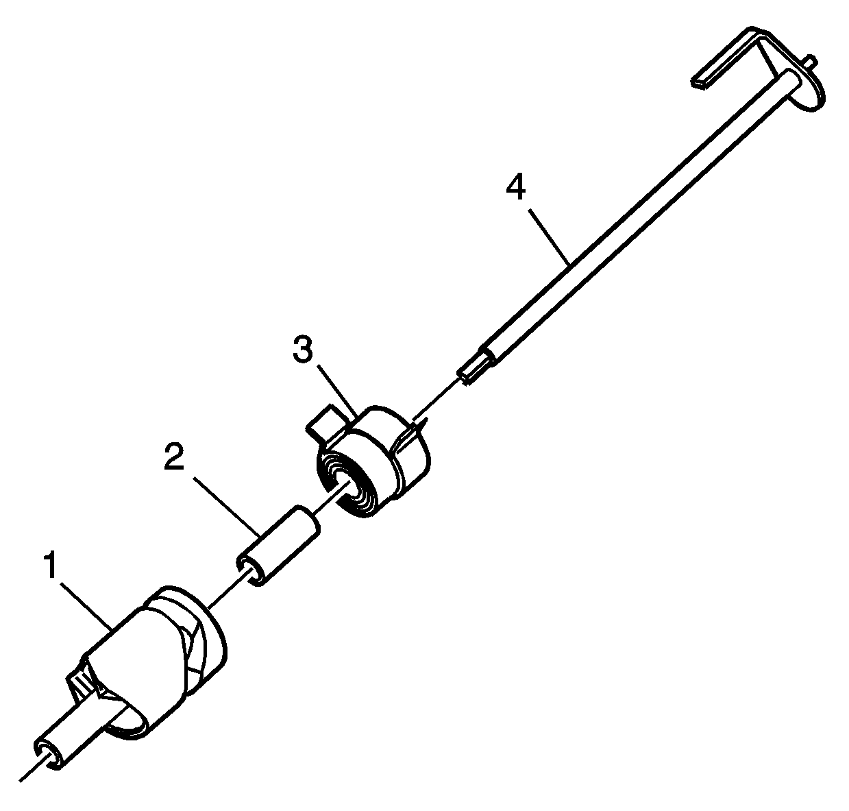
Important: Only disassemble the shift detent lever shaft assembly if replacing
a faulty component. The tip on the end of the shift detent lever shaft
is used for assembly. If the tip is broken off, the shaft can still
be used, but may cause problems aligning with the rear case half during
the assembly procedure.
- Inspect the shift detent lever (1) at the cam surfaces for
the following conditions:
- Inspect the shift detent lever shaft (4) for the following
conditions:
| • | Encoder motor drive end excessively worn |
- Inspect the sleeve (2) for excessive wear or for being
grooved from the spring (3).
- Inspect the spring (3) for being weak or for the tabs being
bent.
- Replace any of the above components if they are found to be faulty.
Refer to
Transfer Case Disassemble
and
Transfer Case Assemble
.


