Exhaust System Replacement LE5/U24XE
Removal Procedure
Warning: Refer to Exhaust Service Warning in the Preface section.
Warning: Refer to Protective Goggles and Glove Warning in the Preface section.
- Raise and support the vehicle. Refer to Lifting and Jacking the Vehicle.
- Install the shipping fastening (1) to the flex pipe.
- Install the shipping fastening (1) to the flex pipe.
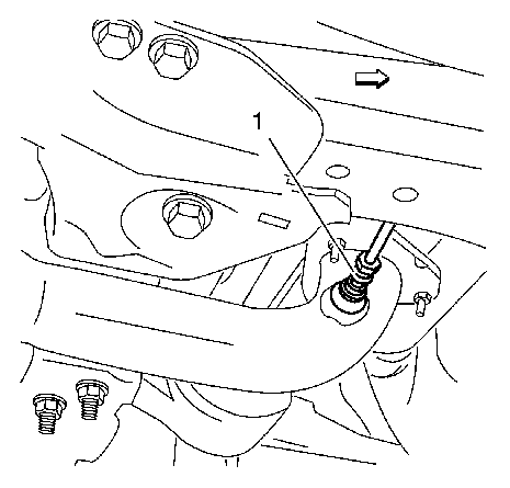
- Disconnect the electrical connector from the heated oxygen sensor 2 (1). Refer to Heated Oxygen Sensor 2 Replacement.
- Remove the exhaust front pipe from the catalytic converter.
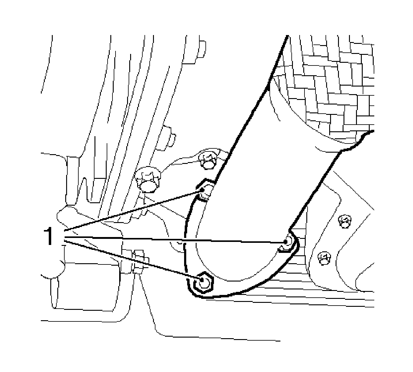
- Remove the three nuts (1) from the exhaust front pipe.
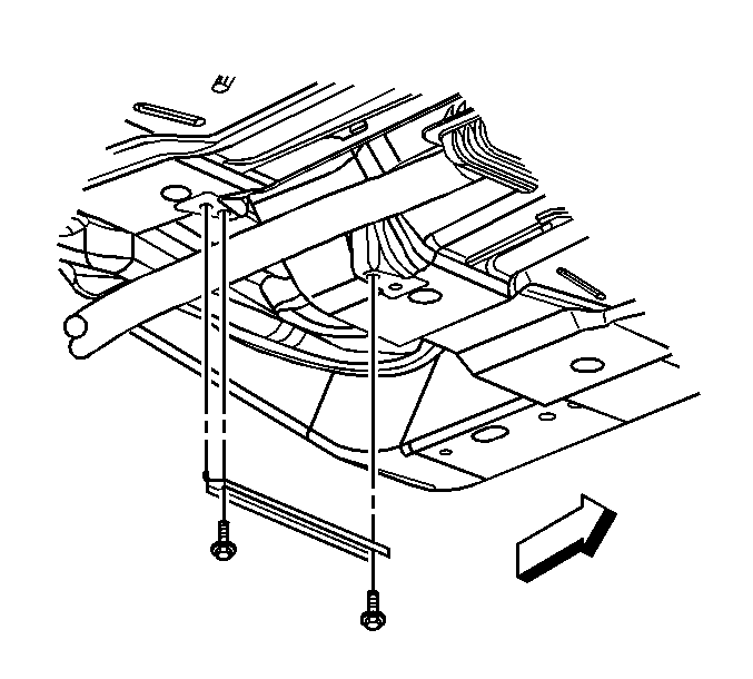
- Remove the floor panel tunnel brace bolts.
- With the aid of an assistant, lower the exhaust system from the vehicle.
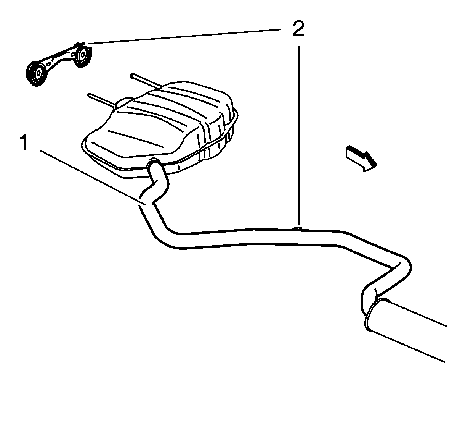
- Remove the exhaust system (1) from the bracket in 3 places (2).
- Remove the heated oxygen sensor 2 of the catalytic converter monitoring device. Refer to Heated Oxygen Sensor 2 Replacement.
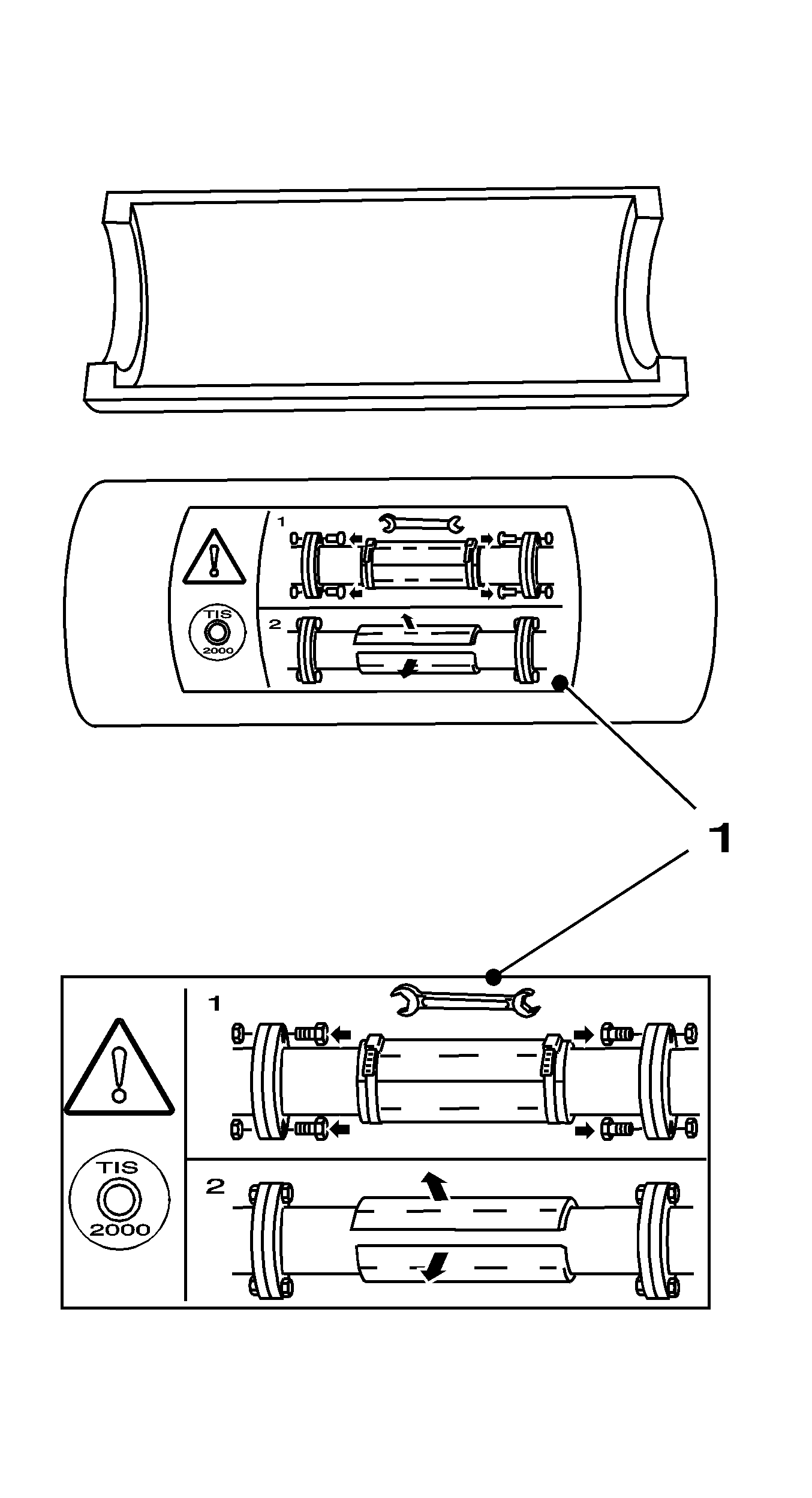
Note: To prevent internal damage to the flexible coupling of the catalytic converter assembly, the converter must be supported. The vertical movement at the rear of the catalytic converter assembly must not exceed 6 degrees up or down.
Note: The fastening clips of the exhaust system should be replaced every time that they are loosened. When replacing the exhaust system, the shipping fastening should only be removed after installation and before starting the engine. The shipping fastening should be removed for other operations in which the exhaust system has to be removed, stored and used to secure the flex pipe.
Installation Procedure
Caution: Refer to Fastener Caution in the Preface section.
- Install the heated oxygen sensor 2 of the catalytic converter monitoring device. Refer to Heated Oxygen Sensor 2 Replacement.
- With the aid of an assistant, install the exhaust system to the vehicle.
- Install the exhaust system (1) to the bracket in 3 places (2).
- Install the floor panel tunnel brace bolts.
- Install the exhaust front pipe to the catalytic converter.
- Install the three nuts (1) to the exhaust front pipe.
- Remove the shipping fastening (1) from the flex pipe.
- Connect the electrial connector to the heated oxygen sensor 2 (1). Refer to Heated Oxygen Sensor 2 Replacement.
- Lower the vehicle.


Tighten
to 25 N·m (18 lb ft).


Exhaust System Replacement LE5/U20XE
Removal Procedure
Warning: Refer to Exhaust Service Warning in the Preface section.
Warning: Refer to Protective Goggles and Glove Warning in the Preface section.
- Raise and support the vehicle. Refer to Lifting and Jacking the Vehicle.
- Install the shipping fastening (1) to the flex pipe.
- See assembly instruction (1) on the shipping fastening.
- Disconnect the electrical connector from the heated oxygen sensor 2 (1). Refer to Heated Oxygen Sensor Replacement - Sensor 2.
- Remove the exhaust front pipe from the catalytic converter.
- Remove the three nuts (1) from the exhaust front pipe.
- Remove the floor panel tunnel brace bolts.
- With the aid of an assistant, lower the exhaust system from the vehicle.
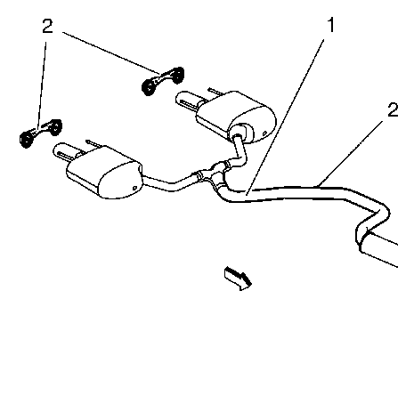
- Remove the exhaust system (1) from the bracket in 3 places (2).
- Remove the heated oxygen sensor 2 of the catalytic converter monitoring device. Refer to Heated Oxygen Sensor Replacement - Sensor 2.

Note: To prevent internal damage to the flexible coupling of the catalytic converter assembly, the converter must be supported. The vertical movement at the rear of the catalytic converter assembly must not exceed 6 degrees up or down.
Note: The fastening clips of the exhaust system should be replaced every time that they are loosened. When replacing the exhaust system, the shipping fastening should only be removed after installation and before starting the engine. The shipping fastening should be removed for other operations in which the exhaust system has to be removed, stored and used to secure the flex pipe.


Installation Procedure
Caution: Refer to Fastener Caution in the Preface section.
- Install the heated oxygen sensor 2 of the catalytic converter monitoring device. Refer to Heated Oxygen Sensor Replacement - Sensor 2.
- With the aid of an assistant, install the exhaust system to the vehicle.
- Install the exhaust system (1) to the bracket in 5 places (2).
- Install the floor panel tunnel brace bolts.
- Install the exhaust front pipe to the catalytic converter.
- Install the three nuts (1) to the exhaust front pipe.
- Remove the shipping fastening (1) from the flex pipe.
- Connect the electrical connector to the heated oxygen sensor 2 (1). Refer to Heated Oxygen Sensor Replacement - Sensor 2.
- Lower the vehicle.


Tighten
to 25 N·m (18 lb ft).


