For 1990-2009 cars only
Special Tools
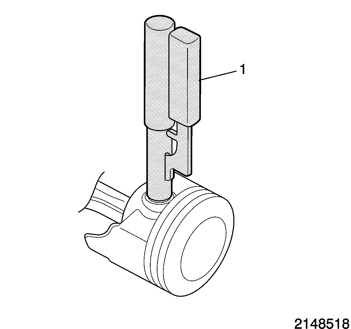
EN-46745 Piston Pin Retainer Remover and Installer
For equivalent regional tools, refer to Special Tools.
- The cast boss (1), on the underside of the piston, must go to the rear of the block.
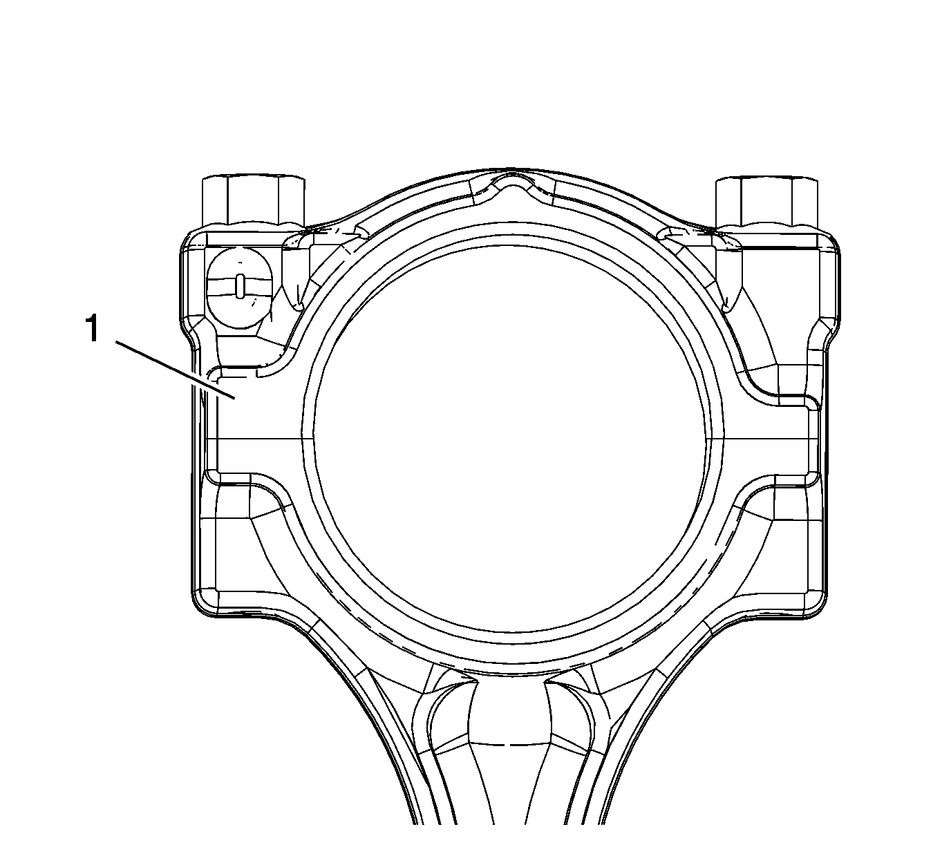
- The larger feature (1), at the split line located on one side of the connecting rod, must go to the front of the block.
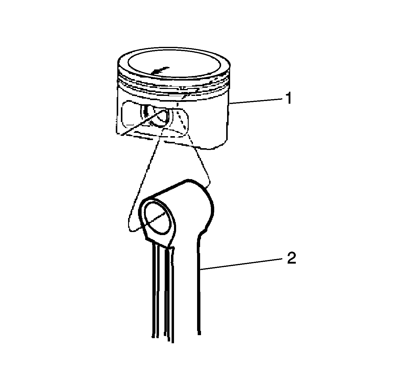
- Assemble the connecting rod (2) and the piston (1).
- Use the following procedure to assemble the piston pin and the retainer:
- Install the following components of the oil control ring assembly (bottom ring):
- Install the lower compression ring (2). Place the manufacturer's mark facing up.
- Install the upper compression ring (1).
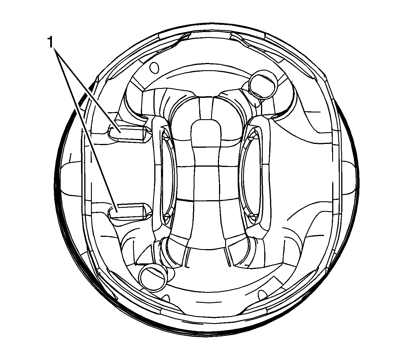
Note: Install the piston onto the connecting rod with the arrow on top of the piston toward the front oriented toward the front of the engine.
Note: The cast boss (1) can be in either or both locations depending on displacement.
Caution: Install the piston pin retainers correctly in the retaining groove during assembly in order to avoid engine damage.
| 4.1. | Coat the piston pin with oil. |
| 4.2. | Install one side of one piston pin retainer into the retaining groove using EN-46745 installer . Rotate the retainer until it is fully seated in the groove. |
| 4.3. | Install the connecting rod and the piston pin. |
Push the piston pin until it bottoms in the previously installed retainer.
| 4.4. | Install the second piston pin retainer, using EN-46745 installer (1). |
| 4.5. | Ensure that the piston moves freely. |
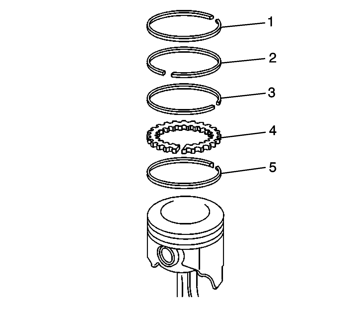
Caution: Use a piston ring expander to install the piston rings. The rings may be damaged if expanded more than necessary.
| 5.1. | The expander (5) |
| 5.2. | The lower oil control ring (4) |
| 5.3. | The upper control ring (3) |
