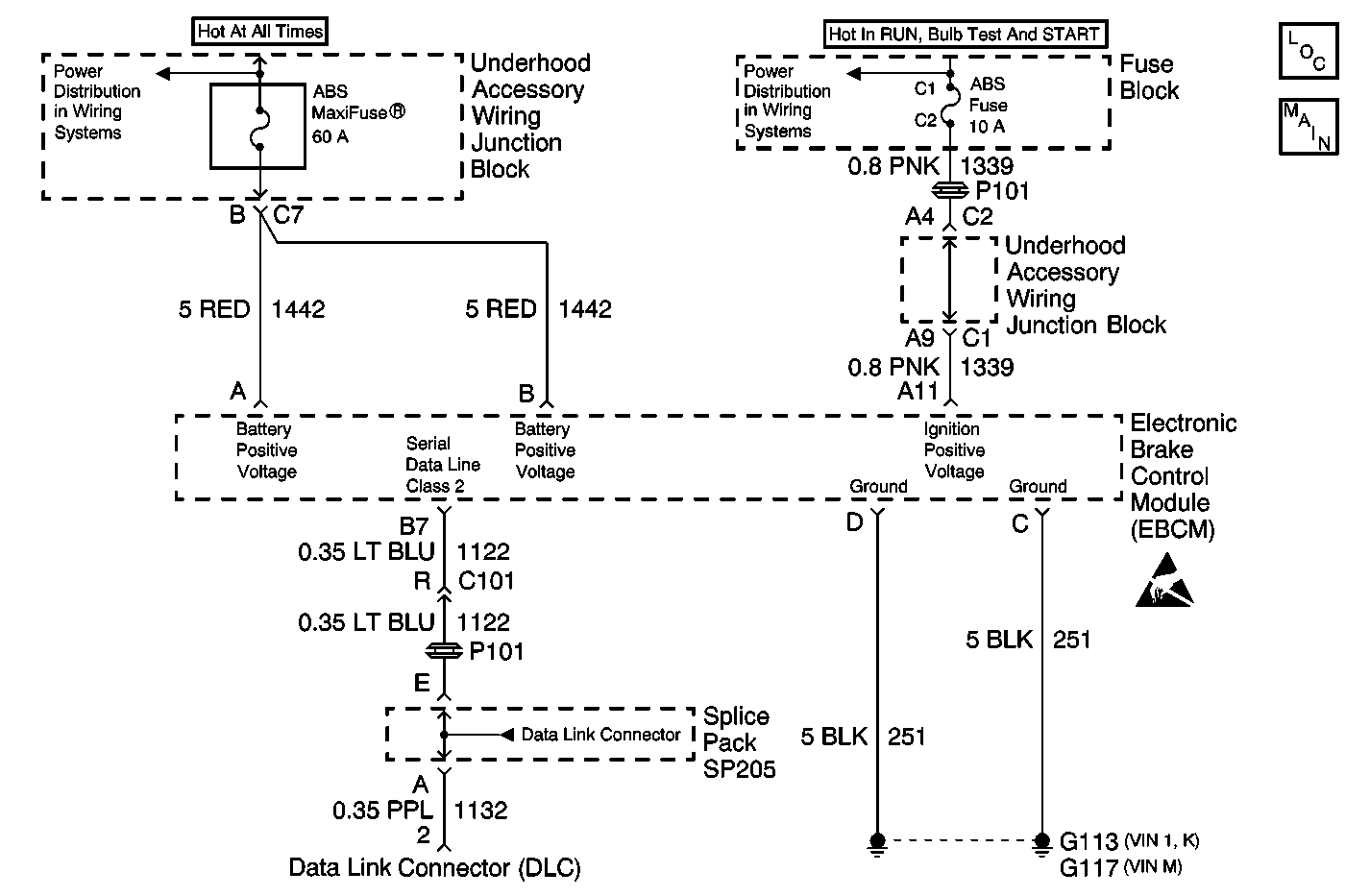
Circuit Description
The Class 2 serial data line allows all the modules on the line to transmit information to each other as needed. Each module is assigned an ID and all the information sent out on the line is assigned a priority by which it is received. When the ignition switch is turned to the run position each module begins to send and receive information. Each module on the Class 2 serial data line knows what information it needs to send out and what information it should be receiving. What the modules do not know is which module is supposed to send them the information. This information is only learned after the module has received the information it needs along with the ID of the module that sent the information. This information is then remembered until the ignition switch is turned off.
Diagnostic Aids
- The following conditions may cause an intermittent malfunction to occur:
- Inspect any circuitry that may cause the intermittent complaint for the following conditions:
| • | A poor connection |
| • | A rubbed-through wire insulation |
| • | A broken wire inside the insulation |
| • | Backed out terminals |
| • | Improper mating |
| • | Broken locks |
| • | Improperly formed terminals |
| • | Damaged terminals |
| • | Poor terminal to wiring connections |
| • | Physical damage to the wiring harness |
Step | Action | Value(s) | Yes | No | ||||
|---|---|---|---|---|---|---|---|---|
1 | Did you perform the ABS Diagnostic System Check? | -- | Go to Step 2 | |||||
2 |
Does the scan tool communicate with any other modules on the class 2 serial data line? | -- | Go to Step 3 | |||||
3 |
Is the voltage within the specified range? | Battery Voltage | Go to Step 4 | Go to Step 7 | ||||
4 | Measure the ignition positive voltage input circuit for the EBCM. Refer to Circuit Testing and Wiring Repairs in Wiring Systems. Is the voltage within the specified range? | Battery Voltage | Go to Step 5 | Go to Step 8 | ||||
5 | Test the module ground circuit for an open. Refer to Circuit Testing and Wiring Repairs in Wiring Systems. Did you find and correct the condition? | -- | Go to Step 20 | Go to Step 6 | ||||
6 | Test the serial data line circuit for an open between the EBCM connector and the Splice Pack SP205. Refer to Circuit Testing and Wiring Repairs in Wiring Systems. Did you find and correct the condition? | -- | Go to Step 20 | Go to Step 15 | ||||
7 | Inspect the Fusible Link (1 GRA) located down at the starter. Is the fuse good? | -- | Go to Step 9 | Go to Step 14 | ||||
8 | Inspect the ABS /PCM Fuse located in the LH IP Accessory Wiring Junction Block. Is the fuse good? | -- | Go to Step 10 | Go to Step 13 | ||||
9 | Measure the voltage at the Fusible Link (1 GRA) by probing between the starter terminal and a good ground. Is the voltage within the specified range? | Battery Voltage | Go to Step 12 | Go to Step 17 | ||||
10 |
Is the voltage within the specified range? | Battery Voltage | Go to Step 11 | Go to Step 16 | ||||
11 | Repair the ignition positive voltage circuit for an open. Refer to Wiring Repairs in Wiring Systems. Did you complete the repair? | -- | Go to Step 20 | -- | ||||
12 | Repair the battery positive voltage circuit for an open. Refer to Wiring Repairs in Wiring Systems. Did you complete the repair? | -- | Go to Step 20 | -- | ||||
13 |
Important: Removing battery voltage or ground from the EBCM will result in the
following conditions:
Did you find and correct the condition? | -- | Go to Step 20 | Go to Step 15 | ||||
14 |
Important: Removing battery voltage or ground from the EBCM will result in the
following conditions:
Did you find and correct the condition? | -- | Go to Step 20 | Go to Step 15 | ||||
15 | Inspect for poor connections at the harness connector of the EBCM. Refer to Testing for Intermittent Conditions and Poor Connections and Connector Repairs in Wiring Systems. Did you find and correct the condition? | -- | Go to Step 20 | Go to Step 18 | ||||
16 | Inspect for poor connections at the harness connector of the LH IP Accessory Wiring Junction Block. Refer to Testing for Intermittent Conditions and Poor Connections and Connector Repairs in Wiring Systems. Did you find and correct the condition? | -- | Go to Step 20 | Go to Step 19 | ||||
17 | Repair a poor connection at the starter terminal connector. Refer to Wiring Repairs in Wiring. Did you complete the repair? | -- | Go to Step 20 | -- | ||||
18 | Replace the EBCM. Refer to Electronic Brake Control Module Replacement Did you complete the repair? | -- | Go to Step 20 | -- | ||||
19 | Replace the LH IP Accessory Wiring Junction Block. Did you complete the repair? | -- | Go to Step 20 | -- | ||||
20 |
Does the DTC reset? | -- | Go to Step 2 | System OK |
