Tools Required
J 41396 Park Lock
Cable Pliers

Notice: Use the correct fastener in the correct location. Replacement fasteners
must be the correct part number for that application. Fasteners requiring
replacement or fasteners requiring the use of thread locking compound or sealant
are identified in the service procedure. Do not use paints, lubricants, or
corrosion inhibitors on fasteners or fastener joint surfaces unless specified.
These coatings affect fastener torque and joint clamping force and may damage
the fastener. Use the correct tightening sequence and specifications when
installing fasteners in order to avoid damage to parts and systems.
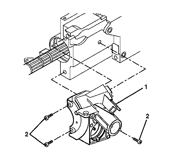
- Install the lock
module assembly (1) and secure using 3 pan head tapping screws (2).
Tighten
Tighten the 3 pan head tapping screws to 7 N·m (62 lb in).

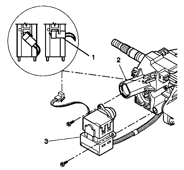
- Install the ignition and
key alarm switch assembly (3) onto the lock module assembly (2).
- Install the 2 tapping screws into the lock module assembly (2).
Tighten
Tighten the 2 tapping screws to 1.5 N·m (13 lb in).
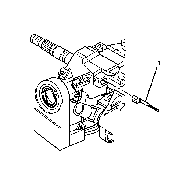
- Install the key alarm connector (1) onto the lock module
assembly (2).
- Install the steering column lock cylinder set only. Refer to
Steering Column Lock Cylinder Set - Assemble - Off Vehicle
.

- Connect the park lock
cable assembly (1) using the following steps:
| • | The lock cylinder should be in the off-lock position. |
| • | The locking tab at the end of the park lock cable assembly (1)
must be installed into the lock module assembly. |

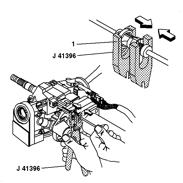
- Adjust the park lock cable
assembly using the following steps:
| 7.1. | Use the shift lever clevis to put the column in the park position. |
| 7.2. | Put the ignition switch in the off-lock position. Remove the key. |
| 7.3. | Unlock the adjuster ring (1) on the park lock cable assembly
with J 41396
. |
| 7.4. | Pull on the cable until the park lock latch contacts the shift
lever clevis. Release the cable. |
| 7.5. | Lock the adjuster ring (1) securely in place on the park
lock cable assembly with J 41396
. |
- Inspect the park lock cable assembly using the following steps:
| 8.1. | Put the lock cylinder in the off-lock position. The shift lever
clevis should not be able to shift out of the park position. |
| 8.2. | Turn the key to the run position and put the shift lever clevis
in the neutral position. |
| 8.3. | With the shift lever clevis in the neutral position the lock cylinder
should not be able to go into the off-lock position. |
| 8.4. | Put the shift lever clevis into the park position. |
| 8.5. | Put the lock cylinder in the off-lock position and then remove
the key. |
- Install the upper tilt head components. Refer to
Steering Column Tilt Head Housing - Assemble - Off Vehicle
.


