| Table 1: | Fuse Types |
| Table 2: | Wire Size Conversion Table |
| Table 3: | Crimp And Seal Splice Chart |
Circuit Protection
Important: After you make any electrical repair, always test the circuit by operating the devices in the circuit. This confirms not only that the repair is correct, but also that the cause of the complaint was correctly identified.
All electrical circuits are protected against excessive loads which might occur because of shorts or overloads in the wiring system. A fuse or circuit breaker provides such protection. A short may cause a fuse to blow or a circuit breaker to open.
Fuses
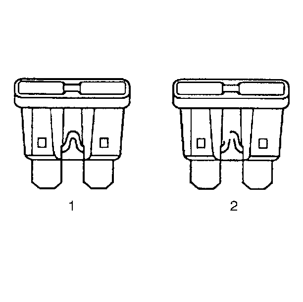
The fuse is the most common method of automotive wiring circuit protection. Whenever there is an excessive amount of current flowing through a circuit the fusible element will melt and create an open or incomplete circuit. Fuses are a "one time" protection device and must be replaced each time the circuit is overloaded. To determine if a fuse is blown, remove the suspect fuse and examine the element in the fuse for a break. If the element is broken, replace the fuse with one of equal current rating.
Current Rating Amperes | Color |
|---|---|
Auto Fuses, Mini Fuses | |
2 | Gray |
3 | Violet |
5 | Tan |
7.5 | Brown |
10 | Red |
15 | Blue |
20 | Yellow |
25 | White |
30 | Green |
Maxi Fuses | |
20 | Yellow |
30 | Light Green |
40 | Orange |
60 | Blue |
Circuit Breakers
A circuit breaker is a protective device that is designed to open the circuit when a current load is in excess of the rated breaker capacity. If there is a short or other type of overload condition in the circuit, the excessive current will open the circuit between the circuit breaker terminals. Two types of circuit breakers are used. The first is a circuit breaker. This type will open when excessive current passes through it for a period of time. It will close again after a few seconds. If the cause of the high current is still present, it will open again. It will continue to cycle open and closed until the condition causing the high current is removed. The second type of circuit breaker is a positive temperature coefficient (PTC) circuit breaker. This type greatly increases its resistance when excessive current passes through it. The excessive current heats the PTC device. As the device heats, its resistance increases. Eventually the resistance gets so high that the circuit is effectively open. Unlike the ordinary circuit breaker, the PTC unit will not reset until the circuit is opened, removing the voltage from its terminals. Once the voltage is removed, the circuit breaker will re-close within a second or two.
Typical Electrical Repairs
An open circuit is an incomplete circuit. Power cannot reach the load or the ground. If a circuit is open, active components do not energize. A short circuit is an unwanted connection between one part of the circuit and either the ground or another part of the circuit. A short circuit causes a fuse to blow or a circuit breaker to open.
Short Circuits Caused by Damaged Wire Insulation
If the damage is minor, locate the problem and tape over the wire. If the damage is more extensive, replace the faulty segment of the wire. Follow the instructions below in order to repair copper and shielded cables.
Metric Wire Sizes (mm²) | AWG Sizes |
|---|---|
0.22 | 24 |
0.35 | 22 |
0.5 | 20 |
0.8 | 18 |
1.0 | 16 |
2.0 | 14 |
3.0 | 12 |
5.0 | 10 |
8.0 | 8 |
13.0 | 6 |
19.0 | 4 |
32.0 | 2 |
50.0 | 1/0 |
Splicing Copper Wire Using Splice Clips
Tools Required
J 38125 Terminal Repair Kit
- Open the harness.
- Cut the wire.
- Strip the insulation.
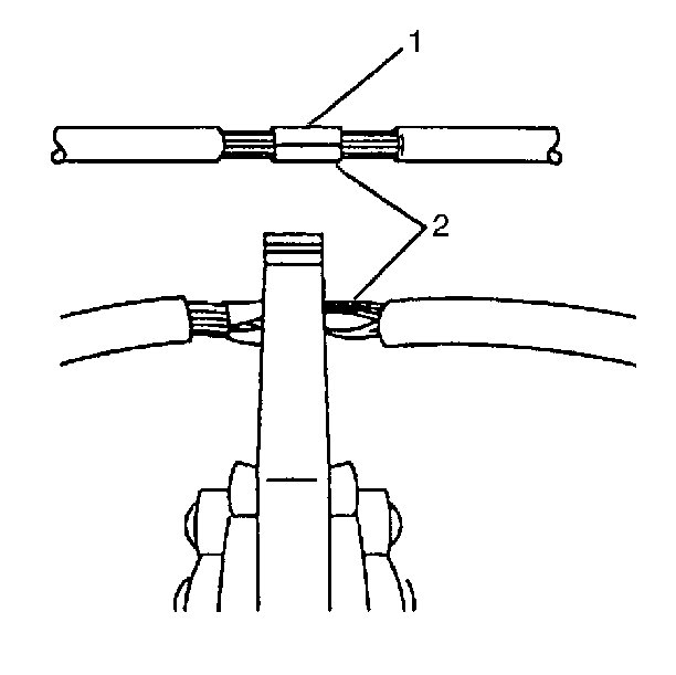
- Crimp the wires.
- Apply steady pressure until the crimp tool closes.
- Crimp the splice on each end.
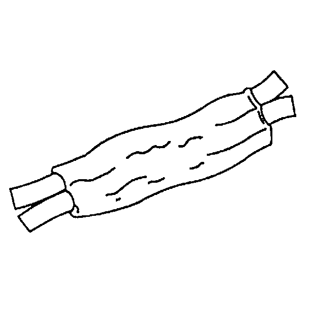
- Apply 60/40 rosin core solder to the opening in the back of the clip. Follow the manufacturer's instructions for the solder equipment.
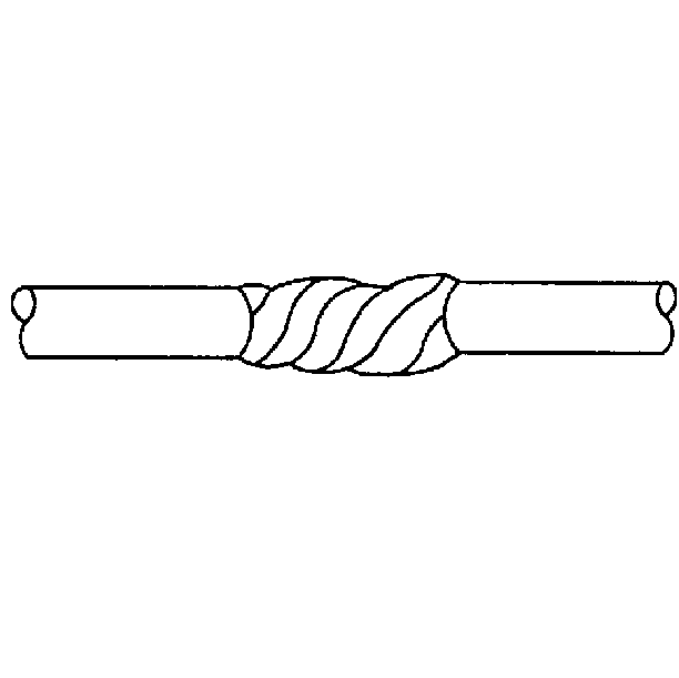
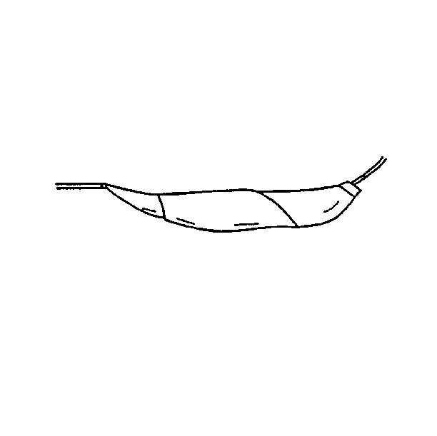
- Tape the splice. Roll on enough tape in order to duplicate the thickness of the insulation on the existing wires.
- You may tape the wire again if the wire does not belong in a conduit or another harness covering. Use a winding motion in order to cover the first piece of tape.
| • | If the harness is taped, remove the tape. |
| • | To avoid wiring insulation damage, use a sewing ripper in order to cut open the harness. |
| • | If the harness has a black plastic conduit, pull out the desired wire. |
| • | Cut as little wire off the harness as possible. |
| • | Ensure that each splice is at least 40 mm (1.5 in) away from other splices, harness branches, and connectors. This will help prevent moisture from bridging adjacent splices and causing damage. |
| • | Use wire of equal or greater size than the original. The wire's insulation must have the same or higher temperature rating. |
| • | You may use general purpose insulation for areas that are not subject to high temperatures. |
| • | Use a cross-linked polyethylene insulated wire for areas where high temperatures are expected. |
| - | Cross-linked polyethylene wire may be used to replace PVC, but you may not replace cross-linked polyethylene with PVC. |
| - | Cross-linked polyethylene wire is not fuel resistant and should not be used to replace wire where there is the possibility of fuel contact. |
| • | Select the correct size opening in the wire stripper or work down from the largest size. |
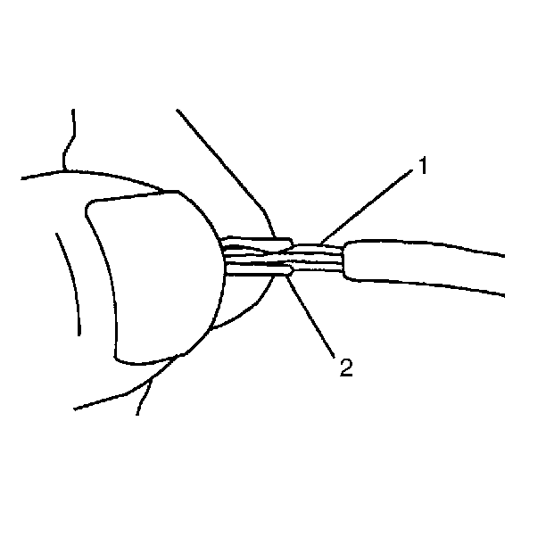
| • | Select the proper clip to secure the splice. Follow the instructions in the J 38125 Kit in order to determine the proper clip size crimp tool and anvil. |
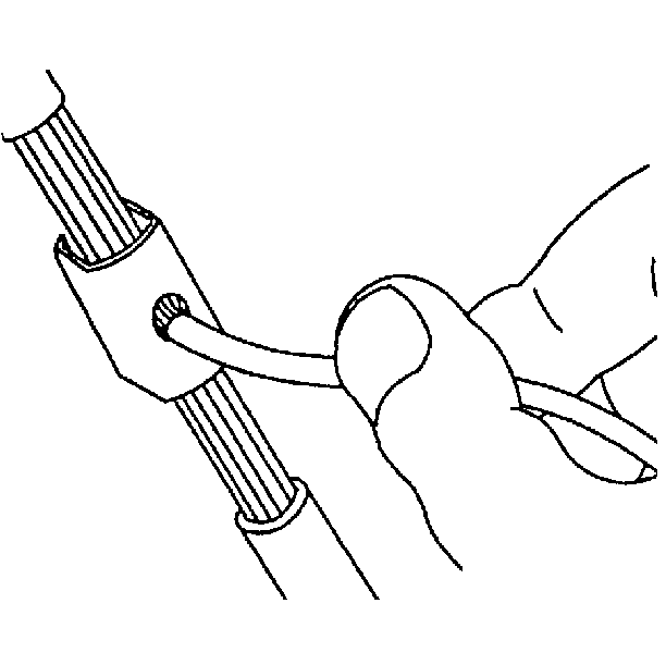
| • | Overlap the two stripped wire ends and hold them between your thumb and forefinger. |
| • | Center the splice clip under the stripped wires and hold it in place. |
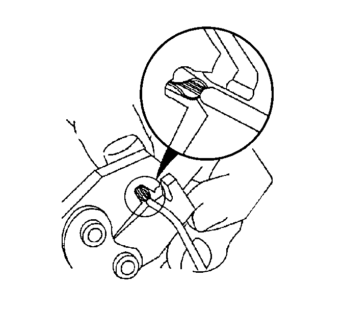
| • | Ensure that the wires extend beyond the clip in each direction. |
| • | Ensure that no strands of wire are cut loose. |
| • | Ensure that no insulation is caught under the clip. |
Splicing Copper Wire Using Crimp and Seal Splice Sleeves
Crimp and seal splice sleeves may be used on all types of insulation except tefzel and coaxial to form a one-to-one splice. They are to be used where there are special requirements such as moisture sealing. Follow the instructions below in order to splice copper wire using crimp and seal splice sleeves.
Color Splice Sleeve | Crimp Tool Nest Color | Wire Gage AWG/ (Metric) |
|---|---|---|
Salmon | Red | 20, 18,/ (0.5, 0.8) |
Blue | Blue | 16, 14 /(1.0, 2.0) |
Yellow | Yellow | 12, 10/(3.0, 5.0) |
- Open the harness.
- Cut the wire.
- Strip the insulation.
- Select the proper splice sleeve according to the wire size.
- Insert the wires into the splice sleeve and crimp.
- Shrink the insulation around the splice.
| • | If the harness is taped, remove the tape. |
| • | To avoid wiring insulation damage, use a sewing ripper in order to cut open the harness. |
| • | If the harness has a black plastic conduit, pull out the desired wire. |
| • | Cut as little wire off the harness as possible. |
| • | Ensure that each splice is at least 40 mm (1.5 in) away from other splices, harness branches, and connectors. This will help prevent moisture from bridging adjacent splices and causing damage. |
| • | Find the correct wire size. |
| • | Select the correct size opening in the wire stripper or work down from the largest size. |
| • | Strip approximately 7.5 mm (5/16 in) of insulation from each wire to be spliced. |
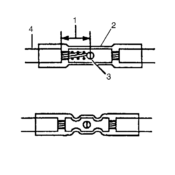
| • | Place the splice tool in the nest so that the crimp falls at point 1 on the splice. The sleeve has a stop in the middle of the barrel in order to prevent the wire from going farther. |
| • | Close the hand crimper handles slightly in order to hold the splice sleeve firmly in the proper nest. |
| • | Insert the wire into the splice until it hits the barrel stop. |
| • | Close the handles of the J 38125 until the crimper handles open when released. The crimper handles will not reopen until the proper amount of pressure is applied to the splice sleeve. |
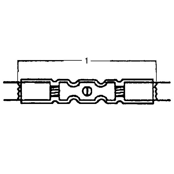
| • | Use a torch in order to apply heat where the barrel is crimped. |
| • | Gradually move the heat barrel to the open end of the tubing, shrinking the tubing as the heat is moved along the insulation. A small amount of sealant will come out of the end of the tubing when sufficient shrinkage is achieved. |
Splicing Twisted/Shielded Cable
Twisted/shielded cable is used in order to protect wiring from electrical noise. Two-conductor cable of this construction is used between the radio and the Delco-Bose® speaker/amplifier units and other applications where low level, sensitive signals must be carried. Follow the instructions below in order to repair the twisted/shielded cable.
- Remove the outer jacket. Use care not to cut into the drain wire of the mylar tape.
- Unwrap the tape. Do not remove the tape. The tape will be used in order to rewrap the twisted conductors after you have made the splice.
- Prepare the splice. Untwist the connectors and follow the splicing instructions for copper wire.
- Re-assemble the cable.
- Tape over the entire cable. Use a winding motion when you apply the tape.
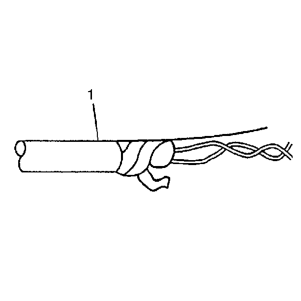
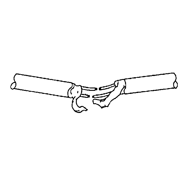
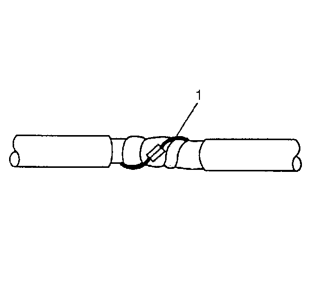
| • | Rewrap the conductors with the mylar tape. |
| • | Use caution not to wrap the drain wire in the tape. |
| • | Follow the splicing instructions for copper wire and splice the drain wire. |
| • | Wrap the drain wire around the conductors and tape with mylar tape. |
